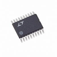
LT3570EFE#PBF Linear Technology, LT3570EFE#PBF Datasheet - Page 15

LT3570EFE#PBF
Manufacturer Part Number
LT3570EFE#PBF
Description
IC PWM BUCK BST DIV CM 20TSSOP
Manufacturer
Linear Technology
Datasheet
1.LT3570EFEPBF.pdf
(20 pages)
Specifications of LT3570EFE#PBF
Topology
Step-Down (Buck) (1), Step-Up (Boost) (1), Linear (LDO) (1)
Function
Automotive
Number Of Outputs
3
Frequency - Switching
500kHz ~ 2.1MHz
Voltage/current - Output 1
Adj to 0.8V, 1.5A
Voltage/current - Output 2
Adj to 0.8V, 1.5A
Voltage/current - Output 3
Controller
W/led Driver
No
W/supervisor
No
W/sequencer
No
Voltage - Supply
2.5 V ~ 36 V
Operating Temperature
-40°C ~ 125°C
Mounting Type
*
Package / Case
20-TSSOP Exposed Pad, 20-eTSSOP, 20-HTSSOP
Frequency-max
2.75MHz
Duty Cycle
95%
Pwm Type
Current Mode
Buck
Yes
Boost
Yes
Flyback
No
Inverting
No
Doubler
No
Divider
Yes
Cuk
No
Isolated
No
Primary Input Voltage
36V
No. Of Outputs
3
Output Current
2.4A
No. Of Pins
20
Operating Temperature Range
-40°C To +125°C
Msl
MSL 1 - Unlimited
Supply Voltage Range
2.1V To 36V
Rohs Compliant
Yes
Lead Free Status / RoHS Status
Lead free / RoHS Compliant
Available stocks
Company
Part Number
Manufacturer
Quantity
Price
APPLICATIONS INFORMATION
compensation resistor, R
50k. A good technique to compensate a new application
is to use a 50k potentiometer in place of R
1nF capacitor for C
observing the transient response, the optimum value for
R
for the circuit of Figure 1 with load current stepped from
100mA to 500mA for the buck converter. Figure 3a shows
the transient response with R
margin is poor as evidenced by the excessive ringing in
the output voltage and inductor current. In Figure 3b,
the value of R
more damped response. Figure 3c shows the result when
R
is nicely damped and the compensation procedure is
complete. The same procedure is used to compensate
the boost converter.
C
C
can be found. Figures 3a to 3c illustrate this process
is increased further to 25k. The transient response
Figure 3a. Transient Response Shows Excessive Ringing
500mA/DIV
V
I
OUT
OUT
C
is increased to 5.75k, which results in a
C
. By adjusting the potentiometer while
C
, is usually in the range of 5k to
200μs/DIV
C
equal to 1.6k. The phase
500mA/DIV
Figure 3c. Transient Response Well Damped
V
I
OUT
OUT
C
, and use a
3570 F03a
200μs/DIV
Soft-Start
The soft-start time is programmed with an external capaci-
tor to ground on SS. An internal current source charges it
with a nominal 4.5μA. The voltage on the soft-start pin is
used to control the feedback voltage. The soft-start time
is determined by the equation:
where C
commanded shutdown, ULVO on the input or a thermal
shutdown, the capacitor is discharged automatically. The
soft-start will remain low and only charge back up after
the fault goes away and the voltage on SS is less than
approximately 100mV.
t
SS
= 0.2 • C
500mA/DIV
SS
V
I
Figure 3b. Transient Response is Better
OUT
OUT
is in nF and t
SS
3570 F03c
SS
200μs/DIV
is in ms. In the event of a
LT3570
3570 F03b
15
3570fb


