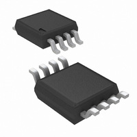
LP2975AIMM-5.0/NOPB National Semiconductor, LP2975AIMM-5.0/NOPB Datasheet - Page 18

LP2975AIMM-5.0/NOPB
Manufacturer Part Number
LP2975AIMM-5.0/NOPB
Description
IC DVR/CTRLR MOSFET LDO 8-MSOP
Manufacturer
National Semiconductor
Type
Positive Fixedr
Datasheet
1.LP2975IMM-5.0NOPB.pdf
(20 pages)
Specifications of LP2975AIMM-5.0/NOPB
Number Of Outputs
1
Voltage - Output
5V
Current - Supply
180µA
Voltage - Input
1.8 ~ 24 V
Operating Temperature
-40°C ~ 125°C
Package / Case
8-MSOP, Micro8™, 8-uMAX, 8-uSOP,
Lead Free Status / RoHS Status
Lead free / RoHS Compliant
Other names
LP2975AIMM-5.0
LP2975AIMM-5.0TR
LP2975AIMM-5.0TR
www.national.com
Application Hints
As shown, moving the location of f
extends the bandwidth, pushing the crossover frequency f
out to about 200 kHz. In viewing the plot, it can be seen that
f
pole and f
will cause enough phase shift to leave very little phase
margin. This application would either oscillate continuously
or be marginally stable (meaning it would exhibit severe
ringing on transient steps).
This can be improved by adding a feed-forward capacitor C
which adds a zero (f
graph HIGH ESR CORRECTED WITH FEED-FORWARD).
In this case, C
frequency as f
due to f
the f
phase margin of
LOW ESR: To illustrate how an output capacitor with low
ESR can cause an LDO regulator to oscillate, the same
example will be shown except that the ESR will be reduced
sufficiently to increase the original f
The plot now shows (see graph LOW ESR UNSTABLE
WITHOUT FEED-FORWARD) that the crossover frequency
f
that the zero f
which is not sufficient for stability.
p
c
has moved down to about 8 kHz. Since f
and f
c
frequency, it will add
High ESR Unstable without Feed-Forward
z
pg
High ESR Corrected with Feed-Forward
essentially cancel out, leaving only the controller
). Assuming the added pole f
pg
. However, since f
z
pg
F
can only provide about 9˚ of phase lead at f
is selected to place f
>
(essentially cancelling out the phase shift
45˚ (adequate for good stability).
zf
) and a pole (f
<
pg
(Continued)
45˚ of phase lag, leaving a
now occurs well before f
z
pf
from 5 kHz to 50 kHz.
) to the gain plot (see
z
zf
pf
lower in frequency
at about the same
is near or beyond
z
is 6X f
10003429
10003431
c
, it means
c
, it
F
c
c
,
,
18
This application can also be improved by adding a feed-
forward capacitor. C
the gain plot (see graph LOW ESR CORRECTED WITH
FEED-FORWARD).
The crossover frequency f
selected so that f
(which means V
erably improved. Calculating out all the poles and zeroes,
the phase margin is increased from 9˚ to 43˚ (adequate for
good stability).
EXCESSIVE GATE CAPACITANCE: Higher values of gate
capacitance shift the pole f
cause stability problems (see previous section GATE CA-
PACITANCE POLE FREQUENCY). As shown in the graph
f
40 kHz and 500 kHz. How much phase shift this adds
depends on the crossover frequency f
The effect of gate capacitance becomes most important at
high values of ESR for the output capacitor (see graph HIGH
ESR UNSTABLE WITHOUT FEED-FORWARD). Higher val-
ues of ESR increase f
positive gain portion of the curve. As f
frequency (corresponding to higher values of gate capaci-
tance), this effect becomes even worse.
This points out why FET’s should be selected with the lowest
possible gate capacitance: it makes the design more tolerant
of higher ESR values on the output capacitor.
The use of a feed-forward capacitor C
excess phase shift due to f
on output voltage (see next section).
pg
vs. C
Low ESR Unstable without Feed-Forward
EFF
Low ESR Corrected with Feed-Forward
, the pole f
OUT
zf
is about 5 kHz, and f
F
= 5V), the phase margin will be consid-
will add both a zero f
pg
c
, which brings f
will likely fall somewhere between
pg
c
pg
to lower frequencies, which can
is now about 10 kHz. If C
, but its effectiveness depends
c
.
pg
F
pf
pg
moves to a lower
will help reduce
zf
is about 20 kHz
10003430
10003432
more into the
and pole f
pf
F
to
is


