ADR512ART-R2 Analog Devices Inc, ADR512ART-R2 Datasheet - Page 4
ADR512ART-R2
Manufacturer Part Number
ADR512ART-R2
Description
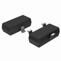
IC REF SHUNT PREC 1.2V SOT-23-3
Manufacturer
Analog Devices Inc
Datasheet
1.ADR512ARTZ-REEL7.pdf
(8 pages)
Specifications of ADR512ART-R2
Rohs Status
RoHS non-compliant
Design Resources
30 V Low Cost DAC Using AD5292 Digital Potentiometer (CN0111) Programmable Bidirectional Current Source Using AD5292 and ADA4091-4 (CN0117) Versatile High Precision Programmable Current Sources Using DACs, Op Amps, and MOSFET Transistors (CN0151)
Reference Type
Shunt
Voltage - Output
1.2V
Tolerance
±0.3%
Temperature Coefficient
60ppm/°C
Number Of Channels
1
Current - Cathode
100µA
Current - Output
10mA
Operating Temperature
-40°C ~ 85°C
Mounting Type
Surface Mount
Package / Case
SOT-23-3, TO-236-3, Micro3™, SSD3, SST3
Voltage - Input
-
Current - Quiescent
-
Other names
ADR512ART-R2TR


ADR512
PARAMETER DEFINITIONS
Temperature Coefficient
This is the change of output voltage with respect to operating
temperature changes, normalized by the output voltage at 25°C.
This parameter is expressed in ppm/°C and can be determined
with the following equation:
where:
V
V
V
Thermal Hysteresis
Thermal hysteresis is defined as the change of output voltage
after the device is cycled through the temperature from +25°C to
–40°C to +85°C and back to +25°C. This is a typical value from
a sample of parts put through such a cycle.
where:
V
V
O
O
O
O
O_TC
(25°C) = V
(T
(T
(25°C) = V
V
V
to –40°C to +85°C and back to +25°C
TCV
1
2
TPC 7. Output Response to 100 µ A Input Current
Change With 1 µ F Capacitor
) = V
) = V
O HYS
O HYS
= V
_
_
O
O
O
O
at 25°C after temperature cycle at +25°C
ppm
[
°
at Temperature 2
at Temperature 1
=
ppm
C
O
O
V
at 25°C
at 25°C
O
=
(
]
25
=
V
V
°
O
C
O
V T
(
)
25
O
(
25
TIME (2 s/DIV)
−
V
( )
V
°
O
°
2
C
O TC
C
(
25
)
_
−
)
×
−
V T
°
(
V
C
T
O
O TC
2
)
( )
V
−
_
OUT
1
T
∆I
1
= 20mV/DIV
IN
)
×
×
= 100 A
10
10
6
6
(1)
(2)
–4–
APPLICATIONS SECTION
The ADR512 is a 1.2 V precision shunt voltage reference. It
is designed to operate without an external output capacitor be-
tween the positive and negative terminals for stability. An external
capacitor can be used for additional filtering of the supply.
As with all shunt voltage references, an external bias resistor
(R
(see Figure 1). R
through the load (I
supply voltage can vary, thus R
•
•
Given these conditions, R
voltage (Vs), the load and operating current (I
ADR512, and the ADR512’s output voltage.
BIAS
R
rent to the ADR512 even when the supply voltage is at its
minimum and the load current is at its maximum value.
R
exceed 10 mA when the supply voltage is at its maximum
and the load current is at its minimum.
R
BIAS
BIAS
) is required between the supply voltage and the ADR512
BIAS
must be small enough to supply the minimum I
also needs to be large enough so that I
=
(V
S
BIAS
TPC 8. 1 Hz to 10 Hz Noise
–
L
V
) and the ADR512 (I
OUT
sets the current that is required to pass
) (I
BIAS
TIME (400ms/DIV)
/
L
is determined by the supply
BIAS
+
I )
Q
is chosen based on
Q
2 V/DIV
). The load and the
L
Q
and I
does not
Q
) of the
REV. 0
Q
cur-
(3)
Related parts for ADR512ART-R2
Image
Part Number
Description
Manufacturer
Datasheet
Request
R

Part Number:
Description:
±1.7g Dual-Axis IMEMS Accelerometer Evaluation Board
Manufacturer:
Analog Devices Inc
Datasheet:

Part Number:
Description:
Inertial Sensor Evaluation System
Manufacturer:
Analog Devices Inc
Datasheet:
Part Number:
Description:
Manufacturer:
Analog Devices Inc
Datasheet:
Part Number:
Description:
Manufacturer:
Analog Devices Inc
Datasheet:
Part Number:
Description:
Manufacturer:
Analog Devices Inc
Datasheet:
Part Number:
Description:
Manufacturer:
Analog Devices Inc
Datasheet:
Part Number:
Description:
Manufacturer:
Analog Devices Inc
Datasheet:
Part Number:
Description:
Manufacturer:
Analog Devices Inc
Datasheet:
Part Number:
Description:
Manufacturer:
Analog Devices Inc
Datasheet:
Part Number:
Description:
Manufacturer:
Analog Devices Inc
Datasheet:
Part Number:
Description:
Manufacturer:
Analog Devices Inc
Datasheet:
Part Number:
Description:
Manufacturer:
Analog Devices Inc
Datasheet:
Part Number:
Description:
Manufacturer:
Analog Devices Inc
Datasheet: