AD581JH Analog Devices Inc, AD581JH Datasheet - Page 3
AD581JH
Manufacturer Part Number
AD581JH
Description
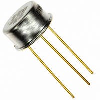
IC PREC VOLT REF 10V TO-5-3
Manufacturer
Analog Devices Inc
Type
Voltage Referencer
Specifications of AD581JH
Temperature Coefficient
30ppm/°C
Reference Type
Series
Voltage - Output
10V
Tolerance
±30mV
Voltage - Input
12 ~ 30 V
Number Of Channels
1
Current - Quiescent
1mA
Current - Output
10mA
Operating Temperature
0°C ~ 70°C
Mounting Type
Through Hole
Package / Case
TO-5-3, Metal Can
Topology
Series
Input Voltage
12V To 30V
Reference Voltage
10V
Reference Voltage Tolerance
30mV
No. Of Pins
3
Operating Temperature Range
0°C To +70°C
Current, Output
10 mA
Current, Quiescent Supply
0.75 mA (Typ.) @ 25 °C
Current, Short Circuit
30 mA (Typ.) @ 25 °C
Current, Supply
0.75 mA
Load Regulation
200 uV⁄mA (Typ.) @ 25 °C
Package Type
TO-5
Power Dissipation
600 mW
Regulation, Line
3 mV
Regulation, Load
200 μV/mA
Standards
MIL-STD-883
Temperature, Operating, Maximum
150 °C
Temperature, Operating, Minimum
-65 °C
Temperature, Operating, Range
-65 to +150 °C
Voltage, Input
15 V
Voltage, Noise
40 μVp-p
Voltage, Output
±13.5 (Max.) @ 25 °C
Voltage, Supply
12 to 30 V
Low Quiescent Current
1.0 mA max
Lead Free Status / RoHS Status
Lead free / RoHS Compliant
Current - Cathode
-
Lead Free Status / Rohs Status
RoHS Compliant part
Electrostatic Device
Available stocks
Company
Part Number
Manufacturer
Quantity
Price

Company:
Part Number:
AD581JH
Manufacturer:
AnalogDevice
Quantity:
270
Part Number:
AD581JH
Manufacturer:
ADI/亚德诺
Quantity:
20 000


ABSOLUTE MAXIMUM RATINGS
Input Voltage . . . . . . . . . . . . . . . . . . . . . . . . . . . . . . . . . . . 40 V
Power Dissipation @ +25°C . . . . . . . . . . . . . . . . . . . . 600 mW
Operating Junction Temperature Range . . . . –55°C to +150°C
Lead Temperature (Soldering 10 sec) . . . . . . . . . . . . . +300°C
Thermal Resistance
APPLYING THE AD581
The AD581 is easy to use in virtually all precision reference
applications. The three terminals are simply primary supply,
ground, and output, with the case grounded. No external com-
ponents are required even for high precision applications; the
degree of desired absolute accuracy is achieved simply by select-
ing the required device grade. The AD581 requires less than
1 mA quiescent current from an operating supply range of
12 to 30 volts.
An external fine trim may be desired to set the output level to
exactly 10.000 volts within less than a millivolt (calibrated to a
main system reference). System calibration may also require a
reference slightly different from 10.00 volts. In either case, the
optional trim circuit shown in Figure 2 can offset the output by
up to ± 30 millivolts (with the 22 Ω resistor), if needed, with
minimal effect on other device characteristics.
Junction-to-Ambient . . . . . . . . . . . . . . . . . . . . . . . 150°C/W
Figure 1. AD581 Pin Configuration (Bottom View)
Figure 2. Optional Fine Trim Configuration
–3–
VOLTAGE VARIATION VS. TEMPERATURE
Some confusion exists in the area of defining and specifying
reference voltage error over temperature. Historically, references
have been characterized using a maximum deviation per degree
Centigrade; i.e., 10 ppm/°C. However, because of nonlinearities
in temperature characteristics, which originated in standard
Zener references (such as “S” type characteristics) most manu-
facturers have begun to use a maximum limit error band approach
to specify devices. This technique involves measurement of the
output at 3, 5 or more different temperatures to guarantee that
the output voltage will fall within the given error band. The
temperature characteristic of the AD581 consistently follows the
S-curve shown in Figure 4. Three-point measurement of each
device guarantees the error band over the specified temperature
range.
The error band which is guaranteed with the AD581 is the
maximum deviation from the initial value at +25°C; this error
band is of more use to a designer than one which simply guaran-
tees the maximum total change over the entire range (i.e., in the
latter definition, all of the changes could occur in the positive
direction). Thus, with a given grade of the AD581, the designer
can easily determine the maximum total error from initial
tolerance plus temperature variation (e.g., for the AD581T,
Figure 4. Typical Temperature Characteristic
Figure 3. Simplified Schematic
AD581
Related parts for AD581JH
Image
Part Number
Description
Manufacturer
Datasheet
Request
R

Part Number:
Description:
±1.7g Dual-Axis IMEMS Accelerometer Evaluation Board
Manufacturer:
Analog Devices Inc
Datasheet:

Part Number:
Description:
Inertial Sensor Evaluation System
Manufacturer:
Analog Devices Inc
Datasheet:
Part Number:
Description:
Manufacturer:
Analog Devices Inc
Datasheet:
Part Number:
Description:
Manufacturer:
Analog Devices Inc
Datasheet:
Part Number:
Description:
Manufacturer:
Analog Devices Inc
Datasheet:
Part Number:
Description:
Manufacturer:
Analog Devices Inc
Datasheet:
Part Number:
Description:
Manufacturer:
Analog Devices Inc
Datasheet:
Part Number:
Description:
Manufacturer:
Analog Devices Inc
Datasheet:
Part Number:
Description:
Manufacturer:
Analog Devices Inc
Datasheet:
Part Number:
Description:
Manufacturer:
Analog Devices Inc
Datasheet:
Part Number:
Description:
Manufacturer:
Analog Devices Inc
Datasheet:
Part Number:
Description:
Manufacturer:
Analog Devices Inc
Datasheet:
Part Number:
Description:
Manufacturer:
Analog Devices Inc
Datasheet: