LT1431CZ#PBF Linear Technology, LT1431CZ#PBF Datasheet - Page 6
LT1431CZ#PBF
Manufacturer Part Number
LT1431CZ#PBF
Description
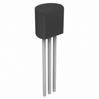
IC REF PROGRAMMABLE .4%TOL TO-92
Manufacturer
Linear Technology
Datasheet
1.LT1431CS8PBF.pdf
(14 pages)
Specifications of LT1431CZ#PBF
Reference Type
Shunt, Adjustable
Voltage - Output
2.5 ~ 36 V
Tolerance
±0.4%
Temperature Coefficient
30ppm/°C
Number Of Channels
1
Current - Cathode
600µA
Current - Output
100mA
Operating Temperature
0°C ~ 70°C
Mounting Type
Through Hole
Package / Case
TO-92-3 (Standard Body), TO-226
Fixed / Adjust / Prog
Adjust
Output Voltage (max)
2.5 to 36V
Reference Voltage Accuracy (max)
0.4
Input Voltage (max)
36V
Operating Temp Range
0C to 70C
Operating Temperature Classification
Commercial
Mounting
Through Hole
Pin Count
3
Package Type
TO-92
Lead Free Status / RoHS Status
Lead free / RoHS Compliant
Voltage - Input
-
Current - Quiescent
-
Lead Free Status / Rohs Status
Compliant
Available stocks
Company
Part Number
Manufacturer
Quantity
Price


pin FuncTions
LT1431
COLL (Pin 1): Open collector of the output transistor. The
maximum pin voltage is 36V. The saturation voltage at
100mA is approximately 1V.
COMP (Pin 2): Base of the driver for the output transis-
tor. This pin allows additional compensation for complex
feedback systems and shutdown of the regulator. It must
be left open if unused.
V
The maximum input voltage is 36V and the minimum to
operate is equal to V
typically 0.6mA.
R
that guarantees 1% accuracy of operation as a 5V shunt
regulator with no external trim. The pin is tied to COLL for
self-contained 5V operation. It may be left open if unused.
See note on parasitic diodes below.
GND-S (Pin 5): Ground reference for the on-chip resis-
tive divider and shunt regulator circuitry except for the
output transistor. This pin allows external current limit
of the output transistor with one resistor between GND-F
(force) and GND-S (sense).
GND-F (Pin 6): Emitter of the output transistor and sub-
strate connection for the die.
block DiagraM
TOP
+
(Pin 3): Bias voltage for the entire shunt regulator.
(Pin 4): Top of the on-chip 5k-5k resistive divider
REF
(2.5V). The quiescent current is
R
REF
MID
8
7
R
TOP
4
5k
5k
GND-SENSE
5
2.5V
+
–
4mA/V
g
m
V
=
+
3
R
between R
contained 5V operation. It may be left open if unused.
REF (Pin 8): Control pin of the shunt regulator with a
2.5V threshold. If V
reduces I
COMP , R
circuits that must not be activated on a continuous basis.
Therefore, the absolute maximum DC voltage on these pins
is 6V, well beyond the normal operating conditions.
As with all bipolar ICs, the LT1431 contains parasitic diodes
which must not be forward biased or else anomalous
behavior will result. Pin conditions to be avoided are R
below R
(except for GND-S).
The following pin definitions apply to the Z package.
CATHODE: Corresponds to COLL and V
ANODE: Corresponds to GND-S and GND-F tied together.
REF: Corresponds to REF .
MID
COMP
(Pin 7): Middle of the on-chip resistive divider string
2
MID
TOP
B
TOP
to 0.2µA typical.
, R
in voltage and any pin below GND-F in voltage
COLLECTOR
MID
GND-FORCE
and GND-S. The pin is tied to REF for self-
, and REF have static discharge protection
1
6
+
> 3V, input bias current cancellation
LT1431 BD
+
tied together.
1431fd
TOP
Related parts for LT1431CZ#PBF
Image
Part Number
Description
Manufacturer
Datasheet
Request
R

Part Number:
Description:
IC REF PROGRAMMABLE .4%TOL TO-92
Manufacturer:
Linear Technology
Datasheet:
Part Number:
Description:
IC REFERENCE PROGR .4%TOL TO-92
Manufacturer:
Linear Technology
Datasheet:
Part Number:
Description:
IC REF PROG .4%TOL ADJ TO92
Manufacturer:
Linear Technology
Datasheet:
Part Number:
Description:
IC REF PROGRAMMABLE .4%TOL TO-92
Manufacturer:
Linear Technology
Datasheet:

Part Number:
Description:
Programmable Reference
Manufacturer:
Linear Technology
Datasheet:
Part Number:
Description:
CD ROM LINEARVIEW DATASHEETS
Manufacturer:
Linear Technology

Part Number:
Description:
Standalone Linear Li-Ion Battery Charger with Thermal Regulation in ThinSOT
Manufacturer:
Linear Technology Corporation
Datasheet:
Part Number:
Description:
Low noise, high frequency, 8th order linear phase lowpass filter
Manufacturer:
Linear Technology Corporation
Datasheet:
Part Number:
Description:
Manufacturer:
Linear Technology Corporation
Datasheet:
Part Number:
Description:
Manufacturer:
Linear Technology Corporation
Datasheet:
Part Number:
Description:
Manufacturer:
Linear Technology Corporation
Datasheet:
Part Number:
Description:
Manufacturer:
Linear Technology Corporation
Datasheet:
Part Number:
Description:
Manufacturer:
Linear Technology Corporation
Datasheet:
Part Number:
Description:
Manufacturer:
Linear Technology Corporation
Datasheet:
Part Number:
Description:
Manufacturer:
Linear Technology Corporation
Datasheet: