LM80CIMT-3/NOPB National Semiconductor, LM80CIMT-3/NOPB Datasheet - Page 11
LM80CIMT-3/NOPB
Manufacturer Part Number
LM80CIMT-3/NOPB
Description
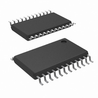
IC MONITOR SYS HARDWAR 24-TSSOP
Manufacturer
National Semiconductor
Series
PowerWise®r
Datasheet
1.LM80CIMT-3NOPB.pdf
(30 pages)
Specifications of LM80CIMT-3/NOPB
Function
Hardware Monitor
Topology
ADC, Comparator, Fan Speed Counter, Register Bank
Sensor Type
External & Internal
Sensing Temperature
-25°C ~ 125°C, External Sensor
Output Type
I²C™
Output Alarm
No
Output Fan
No
Voltage - Supply
2.8 V ~ 5.75 V
Operating Temperature
-25°C ~ 125°C
Mounting Type
Surface Mount
Package / Case
24-TSSOP
Number Of Voltages Monitored
7
Manual Reset
Not Resettable
Watchdog
Watchdog
Battery Backup Switching
No
Power-up Reset Delay (typ)
500 ns
Supply Voltage (max)
5.75 V
Supply Voltage (min)
2.8 V
Supply Current (typ)
200 uA (Typ)
Maximum Operating Temperature
+ 125 C
Mounting Style
SMD/SMT
Minimum Operating Temperature
- 25 C
Power Fail Detection
No
Ic Output Type
Digital
Sensing Accuracy Range
± 3°C
Supply Current
200µA
Supply Voltage Range
2.8V To 5.75V
Resolution (bits)
8bit
Sensor Case Style
TSSOP
No. Of Pins
24
Accuracy %
3°C
Rohs Compliant
Yes
For Use With
LM80EVAL - EVALUATION BOARD FOR LM80
Lead Free Status / RoHS Status
Lead free / RoHS Compliant
Other names
*LM80CIMT-3
*LM80CIMT-3/NOPB
LM80CIMT-3
*LM80CIMT-3/NOPB
LM80CIMT-3


The Serial Bus control lines consists of the SDA (serial data),
SCL (serial clock) and A0-A1 (address) pins. The LM80 can
only operate as a slave. The SCL line only controls the serial
interface, all other clock functions within LM80 such as the
ADC and fan counters are done with a separate asyn-
chronous internal clock.
When using the Serial Bus Interface a write will always consist
of the LM80 Serial Bus Interface Address byte, followed by
the Internal Address Register byte, then the data byte. There
are two cases for a read:
1.
If the Internal Address Register is known to be at the
desired Address, simply read the LM80 with the Serial
Bus Interface Address byte, followed by the data byte
read from the LM80.
(c) Serial Bus Read from a Register with the Internal Address Register Preset to Desired Location
FIGURE 5. Serial Bus Timing
11
2.
The default power on Serial Bus address for the LM80 is: 0101
(A2)(A1)(A0) binary, where A0-A2 reflect the state of the pins
defined by the same names.
All of these communications are depicted in the Serial Bus
Interface Timing Diagrams as shown in
If the Internal Address Register value is unknown, write
to the LM80 with the Serial Bus Interface Address byte,
followed by the Internal Address Register byte. Then
restart the Serial Communication with a Read consisting
of the Serial Bus Interface Address byte, followed by the
data byte read from the LM80.
Figure
5.
www.national.com
10004010
Related parts for LM80CIMT-3/NOPB
Image
Part Number
Description
Manufacturer
Datasheet
Request
R

Part Number:
Description:
Manufacturer:
National Semiconductor
Datasheet:

Part Number:
Description:
Serial Interface ACPI-Compatible Microprocessor System Hardware Monitor
Manufacturer:
NSC [National Semiconductor]
Datasheet:

Part Number:
Description:
IC MONITOR SYS HARDWAR 24-TSSOP
Manufacturer:
National Semiconductor
Datasheet:
Part Number:
Description:
National Semiconductor [8-Bit D/A Converter]
Manufacturer:
National Semiconductor
Datasheet:
Part Number:
Description:
National Semiconductor [Media Coprocessor]
Manufacturer:
National Semiconductor
Datasheet:
Part Number:
Description:
Digitally Controlled Tone and Volume Circuit with Stereo Audio Power Amplifier, Microphone Preamp Stage and National 3D Sound
Manufacturer:
National Semiconductor
Datasheet:
Part Number:
Description:
Digitally Controlled Tone and Volume Circuit with Stereo Audio Power Amplifier, Microphone Preamp Stage and National 3D Sound
Manufacturer:
National Semiconductor
Datasheet:
Part Number:
Description:
AC97 Rev 2 Codec with Sample Rate Conversion and National 3D Sound
Manufacturer:
National Semiconductor
Part Number:
Description:
Manufacturer:
National Semiconductor
Datasheet:
Part Number:
Description:
Manufacturer:
National Semiconductor
Datasheet:
Part Number:
Description:
General Purpose, Low Voltage, Low Power, Rail-to-Rail Output Operational Amplifiers
Manufacturer:
National Semiconductor
Datasheet:
Part Number:
Description:
8-bit 20 MSPS flash A/D converter.
Manufacturer:
National Semiconductor
Datasheet:
Part Number:
Description:
Low Noise Quad Operational Amplifier
Manufacturer:
National Semiconductor
Datasheet:
Part Number:
Description:
Quad Differential Line Receivers
Manufacturer:
National Semiconductor
Datasheet: