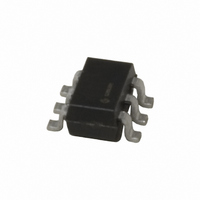
MIC281-7BM6 TR Micrel Inc, MIC281-7BM6 TR Datasheet - Page 6

MIC281-7BM6 TR
Manufacturer Part Number
MIC281-7BM6 TR
Description
IC SUPERVISOR THERMAL SOT23-6
Manufacturer
Micrel Inc
Series
IttyBitty®r
Datasheet
1.MIC281-1YM6_TR.pdf
(12 pages)
Specifications of MIC281-7BM6 TR
Function
Temp Monitoring System (Sensor)
Topology
ADC, Register Bank
Sensor Type
External
Sensing Temperature
External Sensor
Output Type
I²C™/SMBus™
Output Alarm
No
Output Fan
No
Voltage - Supply
3 V ~ 3.6 V
Operating Temperature
-40°C ~ 85°C
Mounting Type
Surface Mount
Package / Case
SOT-23-6
Lead Free Status / RoHS Status
Contains lead / RoHS non-compliant
Other names
MIC281-7BM6TR
MIC281-7BM6TR
MIC281-7BM6TR
Functional Description
Serial Port Operation
The MIC281 uses standard SMBus Write_Byte and Read_Byte
operations for communication with its host. The SMBus
Write_Byte operation involves sending the device’s slave
address (with the R/W bit low to signal a write operation),
followed by a command byte and the data byte. The SMBus
Read_Byte operation is a composite write and read operation:
the host first sends the device’s slave address followed by
the command byte, as in a write operation. A new start bit
must then be sent to the MIC281, followed by a repeat of the
MIC281
DATA
CLK
S 1 0 0 1 X X X
START
MIC281 Slave Address
* The lower nibble contains the die revision level, e.g., Rev 0 = 00h.
Label
TEMP
CONFIG
MFG_ID
DEV_ID
DATA
CLK
S 1 0 0 1 A2 A1 A0 0 A X X X X X X X X A
START
R/W = WRITE
MIC281 Slave Address
0 A X X X X X X X X A S 1
Description
Remote temperature result
Configuration
Manufacturer identification
Device and revision identification
ACKNOWLEDGE
Target Register
R/W = WRITE
Master to slave transfer,
i.e., DATA driven by master.
Master to slave transfer,
i.e., DATA driven by master.
Command Byte
Table 1. MIC281 Register Addresses
Figure 1. Write_Byte Protocol
Figure 2. Read_Byte Protocol
ACKNOWLEDGE
ACKNOWLEDGE
Command Byte
6
slave address with the R/W bit (LSB) set to the high (read)
state. The data to be read from the part may then be clocked
out. These protocols are shown in Figures 1 and 2.
The Command byte is eight bits (one byte) wide. This byte
carries the address of the MIC281 register to be operated
upon. The command byte values corresponding to the various
MIC281 registers are shown in Table 1. Other command byte
values are reserved, and should not be used.
START
ACKNOWLEDGE
MIC281 Slave Address
0 0
Slave to master transfer,
i.e., DATA driven by slave.
Slave to master transfer,
i.e., DATA driven by slave.
1
D7
X X X
Command Byte
Read
FE
FF
01
03
R/W = READ
Data Byte to MIC281
D6
h
h
h
h
D5
Value
D4
1
Write
D3 D2 D1 D0
A X
NOT ACKNOWLEDGE
03
n/a
n/a
n/a
ACKNOWLEDGE
h
Data Read From MIC281
X
X
Power-on
00
/A P
X
Default
h
0x
2A
80
X X X X
NOT ACKNOWLEDGE
(0°C)
STOP
h
h
h
*
November 2004
/A P
STOP


