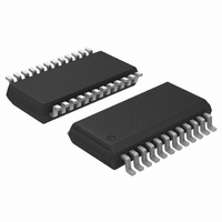
ADT7476AARQZ-R ON Semiconductor, ADT7476AARQZ-R Datasheet - Page 50

ADT7476AARQZ-R
Manufacturer Part Number
ADT7476AARQZ-R
Description
IC REMOTE THERMAL CTLR 24-QSOP
Manufacturer
ON Semiconductor
Series
dBCool®r
Datasheet
1.ADT7476AARQZ.pdf
(67 pages)
Specifications of ADT7476AARQZ-R
Function
Fan Control, Temp Monitor
Topology
ADC, Comparator, Fan Speed Counter, Multiplexer, Register Bank
Sensor Type
External & Internal
Sensing Temperature
-40°C ~ 125°C, External Sensor
Output Type
SMBus™
Output Alarm
No
Output Fan
Yes
Voltage - Supply
3 V ~ 3.6 V
Operating Temperature
-40°C ~ 125°C
Mounting Type
Surface Mount
Package / Case
24-QSOP
Full Temp Accuracy
+/- 0.5 C
Digital Output - Bus Interface
Serial (3-Wire, 4-Wire)
Maximum Operating Temperature
+ 125 C
Minimum Operating Temperature
- 40 C
Lead Free Status / RoHS Status
Lead free / RoHS Compliant
1. A THERM event always overrides any fan setting (even when fans are disabled).
2. This register becomes read-only when the Configuration Register 1 lock bit is set to 1. Any subsequent attempts to write to this register fail.
1. This register becomes read-only when the Configuration Register 1 lock bit is set to 1. Any subsequent attempts to write to this register fail.
1. If the extended resolution bits of these readings are also being read, the extended resolution registers (Register 0x76, Register 0x77) must
2. If V
3. V
1. If the extended resolution bits of these readings are also being read, the extended resolution registers (Register 0x76, Register 0x77) must
2. These temperature readings can be in twos complement or Offset 64 format; this interpretation is determined by Bit 0 of Configuration
3. In twos complement mode, a temperature reading of −128°C (0x80) indicates a diode fault (open or short) on that channel.
4. In Offset 64 mode, a temperature reading of −64°C (0x00) indicates a diode fault (open or short) on that channel.
Table 15. Register 0x10 — Configuration Register 6 (Power−On Default = 0x00)
Table 16. Register 0x11 — Configuration Register 7 (Power−On Default = 0x00)
Table 17. Voltage Reading Registers (Power−On Default = 0x00)
Table 18. Temperature Reading Registers (Power−On Default = 0x80)
Bit No.
Bit No.
Register Address
[7:1]
be read first. Once the extended resolution registers have been read, the associated MSB reading registers are frozen until read. Both the
extended resolution registers and the MSB registers are frozen.
be read first. Once the extended resolution registers have been read, all associated MSB reading registers are frozen until read. Both the
extended resolution registers and the MSB registers are frozen.
Register 5 (0x7C).
[0]
[1]
[2]
[3]
[4]
[5]
[6]
[7]
[0]
Register Address
CC
CCP
(Pin 4) is the supply voltage for the ADT7476A.
0x20
0x21
0x22
0x23
0x24
Low (Bit 7 of 0x40) is set, V
0x25
0x26
0x27
DisTHERM
Mnemonic
Mnemonic
THERM in
V
ExtraSlow
Remote 1
Remote 2
MasterEn
Reserved
SlowFan
SlowFan
SlowFan
SlaveEn
Manual
CCP
Local
Hys
Low
Read−only
Read−only
Read−only
Read−only
Read−only
Read/Write
R/W
Read−only
Read−only
Read−only
R/W
R/W
R/W
R/W
R/W
R/W
R/W
R/W
R/W
R/W
N/A
R/W
CCP
Reflects the voltage measurement at the 2.5 V input on Pin 22 (8 MSBs of reading).
Reflects the voltage measurement (Note 2) at the V
Reflects the voltage measurement (Note 3) at the V
Reflects the voltage measurement at the 5.0 V input on Pin 20 (8 MSBs of reading).
Reflects the voltage measurement at the 12 V input on Pin 21 (8 MSBs of reading).
can control the sleep state of the ADT7476A.
When this bit is set, Fan 1 smoothing times are multiplied x4 for Remote 1 temperature
channel (as defined in Register 0x62).
When this bit is set, Fan 2 smoothing times are multiplied x4 for local temperature channel
(as defined in Register 0x63).
When this bit is set, Fan 3 smoothing times are multiplied x4 for Remote 2 temperature
channel (as defined in Register 0x63).
When this bit is set, THERM is enabled in manual mode. (Note 1)
Setting this bit configures the ADT7476A as a slave for use in fan sync mode.
Setting this bit configures the ADT7476A as a master for use in fan sync mode.
V
drops below its V
Everything is re-enabled once V
above the low limit:
When this bit is set, all fan smoothing times are increased by a further 39.2%
Setting this bit to 1 disables THERM hysteresis.
Reserved. Do not write to these bits.
CCP
Status Bit 1 in Interrupt Status Register 1 is set.
SMBALERT is generated, if enabled.
PROCHOT monitoring is disabled.
PROCHOT monitoring is enabled.
Fans return to their programmed state after a spin-up cycle.
Remote 1 temperature reading (Note 3 and 4) (8 MSBs of reading).
Local temperature reading (8 MSBs of reading).
Remote 2 temperature reading (Note 3 and 4) (8 MSBs of reading).
Low = 1. When the power is supplied from 3.3 V STANDBY and the core voltage (V
http://onsemi.com
CCP
low limit value (Register 0x46), the following occurs:
50
CCP
(Note 1)
increases above the V
Description
(Note 1. 2 and 3)
Description
Description
Description
CCP
CC
(Note 1)
(Note 1 and 2)
input on Pin 4 (8 MSBs of reading).
input on Pin 23 (8 MSBs of reading).
CCP
low limit.When V
CCP
increases
CCP
)


