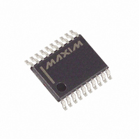
MAX6636UP9A+ Maxim Integrated Products, MAX6636UP9A+ Datasheet - Page 12

MAX6636UP9A+
Manufacturer Part Number
MAX6636UP9A+
Description
IC PREC TEMP MONITOR 7CH 20TSSOP
Manufacturer
Maxim Integrated Products
Datasheet
1.MAX6636UP9A.pdf
(18 pages)
Specifications of MAX6636UP9A+
Function
Temp Monitoring System (Sensor)
Topology
ADC, Buffer, Register Bank
Sensor Type
External & Internal
Sensing Temperature
-40°C ~ 125°C, External Sensor
Output Type
SMBus™
Output Alarm
Yes
Output Fan
Yes
Voltage - Supply
3 V ~ 5.5 V
Operating Temperature
-40°C ~ 125°C
Mounting Type
Surface Mount
Package / Case
20-TSSOP
Full Temp Accuracy
- 0.1 C, 3 C
Digital Output - Bus Interface
Serial (2-Wire)
Digital Output - Number Of Bits
11 bit
Maximum Operating Temperature
+ 125 C
Minimum Operating Temperature
- 40 C
Lead Free Status / RoHS Status
Lead free / RoHS Compliant
7-Channel Precision Temperature Monitor
cases, the alert is cleared even if the fault condition
exists, but the ALERT output reasserts at the end of the
next conversion. The bits indicating the fault for the
OVERT interrupt output clear only on reading the status 2
register even if the fault conditions still exist. Reading the
status 2 register does not clear the OVERT interrupt out-
put. To eliminate the fault condition, either the measured
temperature must drop below the temperature threshold
minus the hysteresis value (4°C), or the trip temperature
must be set at least 4°C above the current temperature.
The MAX6636 directly measures the die temperature of
CPUs and other ICs that have on-chip temperature-
sensing diodes (see the Typical Application Circuit ) or
Table 4. Configuration 1 Register
Table 5. Configuration 2 Register
12
7 (MSB)
7 (MSB)
BIT
______________________________________________________________________________________
BIT
6
5
4
3
2
1
0
6
5
4
3
2
1
0
Mask Local ALERT
Applications Information
Fast remote 1
Mask ALERT 6
Mask ALERT 5
Mask ALERT 4
Mask ALERT 3
Mask ALERT 2
Mask ALERT 1
cancellation
Resistance
TIMEOUT
Reserved
Reserved
Reserved
Reserved
NAME
STOP
POR
NAME
Remote-Diode Selection
STATE
POR
STATE
0
0
0
0
0
0
0
0
POR
0
0
0
0
0
0
0
0
Standby-Mode Control Bit. If STOP is set to logic 1, the MAX6636 stops
converting and enters standby mode.
Reset Bit. Set to logic 1 to put the device into its power-on state. This bit is self-
clearing.
Timeout Enable Bit. Set to logic 0 to enable SMBus timeout.
Channel 1 Fast-Conversion Bit. Set to logic 1 to enable fast conversion of
channel 1.
Resistance Cancellation Bit. When set to logic 1, the MAX6636 cancels series
resistance in the channel 1 thermal diode.
—
—
—
—
Local Alert Mask. Set to logic 1 to mask local channel ALERT.
Channel 6 Alert Mask. Set to logic 1 to mask channel 6 ALERT.
Channel 5 Alert Interrupt Mask. Set to logic 1 to mask channel 5 ALERT.
Channel 4 Alert Mask. Set to logic 1 to mask channel 4 ALERT.
Channel 3 Alert Interrupt Mask. Set to logic 1 to mask channel 3 ALERT.
Channel 2 Alert Mask. Set to logic 1 to mask channel 2 ALERT.
Channel 1 Alert Mask. Set to logic 1 to mask channel 1 ALERT.
it can measure the temperature of a discrete diode-
connected transistor.
The accuracy of the remote temperature measure-
ments depends on the ideality factor (n) of the remote
“diode” (actually a transistor). The MAX6636 is opti-
mized for n = 1.015. A thermal diode on the substrate
of an IC is normally a pnp with the base and emitter
brought out the collector (diode connection) grounded.
DXP_ must be connected to the anode (emitter) and
DXN_ must be connected to the cathode (base) of this
pnp. If a sense transistor with an ideality factor other
than 1.015 is used, the output data is different from the
data obtained with the optimum ideality factor.
Fortunately, the difference is predictable. Assume a
remote-diode sensor designed for a nominal ideality
FUNCTION
FUNCTION
Effect of Ideality Factor


