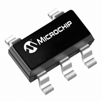
MCP9800A5T-M/OT Microchip Technology, MCP9800A5T-M/OT Datasheet - Page 13

MCP9800A5T-M/OT
Manufacturer Part Number
MCP9800A5T-M/OT
Description
IC SENSOR THERMAL 2.7V SOT235
Manufacturer
Microchip Technology
Datasheets
1.MCP9800A0T-MOT.pdf
(42 pages)
2.MCP9800A0T-MOT.pdf
(4 pages)
3.MCP9801-MSN.pdf
(30 pages)
Specifications of MCP9800A5T-M/OT
Function
Temp Monitoring System (Sensor)
Topology
ADC (Sigma Delta), Register Bank
Sensor Type
Internal
Sensing Temperature
-55°C ~ 125°C
Output Type
I²C™/SMBus™
Output Alarm
No
Output Fan
Yes
Voltage - Supply
2.7 V ~ 5.5 V
Operating Temperature
-55°C ~ 125°C
Mounting Type
Surface Mount
Package / Case
SOT-23-5, SC-74A, SOT-25
Temperature Threshold
Programmable
Full Temp Accuracy
3 C
Digital Output - Bus Interface
I2C, SMBus
Digital Output - Number Of Bits
9 to 12
Supply Voltage (max)
5.5 V
Supply Voltage (min)
2.7 V
Description/function
High-Accuracy 12-bit Serial Input/Output - Thermal Monitors
Maximum Operating Temperature
+ 125 C
Minimum Operating Temperature
- 55 C
Supply Current
400 uA
For Use With
MCP9800DM-TS1 - DEMO BOARD TEMP SENSOR MCP9800
Lead Free Status / RoHS Status
Lead free / RoHS Compliant
Other names
MCP9800A5T-M/OTTR
Available stocks
Company
Part Number
Manufacturer
Quantity
Price
4.3.4
The MCP9800/1/2/3 has an 8-bit read/write configura-
tion register (CONFIG) that allows the user to select the
different features. These features include shutdown,
ALERT output select as comparator or interrupt output,
ALERT output polarity, fault queue cycle, temperature
measurement resolution and One-shot mode (single
conversion while in shutdown). These functions are
described in detail in the following sections.
REGISTER 4-5:
2004 Microchip Technology Inc.
bit 7
bit 5-6
bit 3-4
bit 2
bit 1
bit 0
SENSOR CONFIGURATION
REGISTER (CONFIG)
CONFIGURATION REGISTER (CONFIG)
ONE-SHOT bit
1 = Enabled
0 = Disabled (Power-up default)
00 = 9 bit (Power-up default)
01 = 10 bit
10 = 11 bit
11 = 12 bit
FAULT QUEUE bit
00 = 1 (Power-up default)
01 = 2
10 = 4
11 = 6
ALERT POLARITY bit
1 = Active-High
0 = Active-Low (Power-up default)
COMP/INT bit
1 = Interrupt Mode
0 = Comparator Mode (Power-up default)
SHUTDOWN bit
1 = Enable
0 = Disable (Power-up default)
Legend:
R = Readable bit
- n = Value at POR
bit 7
One-Shot
R/W-0
ADC RESOLUTION bit
R/W-0
Resolution
R/W-0
W = Writable bit
‘1’ = Bit is set
R/W-0
Fault Queue
U = Unimplemented bit, read as ‘0’
‘0’ = Bit is cleared
R/W-0
MCP9800/1/2/3
Polarity
ALERT
R/W-0
x = Bit is unknown
COMP/
R/W-0
INT
DS21909B-page 13
R/W-0
Shut-
down
bit 0


