AD636JHZ Analog Devices Inc, AD636JHZ Datasheet - Page 9
AD636JHZ
Manufacturer Part Number
AD636JHZ
Description
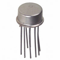
IC CONV RMS-DC LOW LVL TO100-10
Manufacturer
Analog Devices Inc
Datasheet
1.AD636JDZ.pdf
(16 pages)
Specifications of AD636JHZ
Current - Supply
800µA
Voltage - Supply
±2.5 V ~ 16 V
Mounting Type
Through Hole
Package / Case
TO-100, Metal Can (10 Leads)
Accuracy %
1%
Bandwidth
130kHz
Supply Current
800µA
Power Dissipation Pd
500mW
Supply Voltage Range
2V, 5V To 24V
Digital Ic Case Style
TO-100
No. Of Pins
10
Lead Free Status / RoHS Status
Lead free / RoHS Compliant
Available stocks
Company
Part Number
Manufacturer
Quantity
Price
Company:

Part Number:
AD636JHZ
Manufacturer:
REALTEK
Quantity:
2 760


The 2-pole post filter uses an active filter stage to provide even
greater ripple reduction without substantially increasing the
settling times over a circuit with a 1-pole filter. The values of
C
settling times for a constant amount of ripple. Caution should
be exercised in choosing the value of C
is dependent upon this value and is independent of the post
filter. For a more detailed explanation of these topics, refer to
the
+V
RMS MEASUREMENTS
AD636 Principle of Operation
The AD636 embodies an implicit solution of the rms equation
that overcomes the dynamic range as well as other limitations
inherent in a straightforward computation of rms. The actual
computation performed by the AD636 follows the equation:
Figure 12 is a simplified schematic of the AD636; it is
subdivided into four major sections: absolute value circuit
(active rectifier), squarer/divider, current mirror, and buffer
amplifier. The input voltage, V
converted to a unipolar current I1, by the active rectifier A1,
AV
S
, C2, and C3 can then be reduced to allow extremely fast
RMS-to-DC Conversion Application
–V
BUF OUT
+
V
V
0.1
C
10
IN
BUF IN
C2
1
–
rms
10
C
–V
Figure 11. Performance Features of Various Filter Types
NC
dB
AV
V
+
–
S
IN
=
1
2
3
4
5
6
7
Avg
AD636
NC = NO CONNECT
p-p RIPPLE
(ONE POLE)
C
C2 = 4.7µF
AV
+
– BUF
×
10kΩ
ABSOLUTE
SQUARER
CURRENT
= 1µF
DIVIDER
MIRROR
⎡
⎢
⎢
⎣
VALUE
Figure 10. 2-Pole Post Filter
10kΩ
V
Rx
V
DC ERROR
C
(ALL FILTERS)
100
AV
p-p RIPPLE
(TWO POLE)
C
IN
rms
AV
10kΩ
2
= 1µF
FREQUENCY (Hz)
= 1µF, C2 = C3 = 4.7µF
⎤
⎥
⎥
⎦
IN
14
13
12
11
10
9
8
, which can be ac or dc, is
+V
p-p RIPPLE
C
(STANDARD CONNECTION)
NC
NC
NC
COM
R
I
C3
S
OUT
AV
L
= 1µF
+V
–
+
AV
(FOR SINGLE POLE, SHORT Rx,
REMOVE C3)
Guide, 2nd Edition.
1k
, because the dc error
V
rms
OUT
10k
Rev. D | Page 9 of 16
A2. I1 drives one input of the squarer/divider, which has the
transfer function:
The output current, I4, of the squarer/divider drives the current
mirror through a low-pass filter formed by R1 and the externally
connected capacitor, C
greater than the longest period of the input signal, then I4 is
effectively averaged. The current mirror returns a current I3,
which equals Avg. [I4], back to the squarer/divider to complete
the implicit rms computation. Therefore,
The current mirror also produces the output current, I
which equals 2I4. I
voltage with R2 and buffered by A4 to provide a low impedance
voltage output. The transfer function of the AD636 thus results
The dB output is derived from the emitter of Q
voltage at this point is proportional to –log V
Q5, buffers and level shifts this voltage, so that the dB output
voltage is zero when the externally supplied emitter current
(I
THE AD636 BUFFER AMPLIFIER
The buffer amplifier included in the AD636 offers the user
additional application flexibility. It is important to understand
some of the characteristics of this amplifier to obtain optimum
performance. Figure 13 shows a simplified schematic of the buffer.
Because the output of an rms-to-dc converter is always positive,
it is not necessary to use a traditional complementary Class AB
output stage. In the AD636 buffer, a Class A emitter follower is
used instead. In addition to excellent positive output voltage
V
IN
REF
1
) to Q5 approximates I3.
V
I4
I4
OUT
10kΩ
R3
=
=
VOLTAGE–CURRENT
ABSOLUTE VALUE/
= 2 R2 I rms = V
Avg
I1
I3
CONVERTER
20kΩ
A1
2
R4
8kΩ
×
⎡
⎢
⎣
+
8kΩ
I2
I4
OUT
Figure 12. Simplified Schematic
2
⎤
⎥
⎦
can be used directly or converted to a
|V
AV
R4
=
A2
IN
. If the R1, C
|
I1
IN
rms
I1
rms
ONE-QUADRANT
Q1
SQUARER/
DIVIDER
Q2
10µA
A3
FS
CURRENT MIRROR
Q4
AV
Q3
25kΩ
I3
time constant is much
R1
I4
IN
4
C
Q5
. Emitter follower,
AV
BUF
IN
7
I
3
OUT
, because the
8
I
BUFFER
REF
20µA
FS
A4
10kΩ
C
10kΩ
AV
R2
AD636
OUT
14
10
9
5
6
3
,
+V
COM
R
+V
dB
OUT
BUF
OUT
–V
L
S
S
S
Related parts for AD636JHZ
Image
Part Number
Description
Manufacturer
Datasheet
Request
R

Part Number:
Description:
±1.7g Dual-Axis IMEMS Accelerometer Evaluation Board
Manufacturer:
Analog Devices Inc
Datasheet:

Part Number:
Description:
Inertial Sensor Evaluation System
Manufacturer:
Analog Devices Inc
Datasheet:
Part Number:
Description:
Manufacturer:
Analog Devices Inc
Datasheet:
Part Number:
Description:
Manufacturer:
Analog Devices Inc
Datasheet:
Part Number:
Description:
Manufacturer:
Analog Devices Inc
Datasheet:
Part Number:
Description:
Manufacturer:
Analog Devices Inc
Datasheet:
Part Number:
Description:
Manufacturer:
Analog Devices Inc
Datasheet:
Part Number:
Description:
Manufacturer:
Analog Devices Inc
Datasheet:
Part Number:
Description:
Manufacturer:
Analog Devices Inc
Datasheet:
Part Number:
Description:
Manufacturer:
Analog Devices Inc
Datasheet:
Part Number:
Description:
Manufacturer:
Analog Devices Inc
Datasheet:
Part Number:
Description:
Manufacturer:
Analog Devices Inc
Datasheet:
Part Number:
Description:
Manufacturer:
Analog Devices Inc
Datasheet: