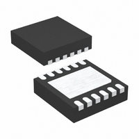
LTC2953CDD-2#TRPBF Linear Technology, LTC2953CDD-2#TRPBF Datasheet - Page 12

LTC2953CDD-2#TRPBF
Manufacturer Part Number
LTC2953CDD-2#TRPBF
Description
IC PB ON/OFF CONTROLLER 12DFN
Manufacturer
Linear Technology
Datasheet
1.LTC2953CDD-1PBF.pdf
(20 pages)
Specifications of LTC2953CDD-2#TRPBF
Applications
Push Button, On/Off Controller
Voltage - Supply
2.7 V ~ 27 V
Current - Supply
14µA
Operating Temperature
0°C ~ 70°C
Mounting Type
Surface Mount
Package / Case
12-DFN
Lead Free Status / RoHS Status
Lead free / RoHS Compliant
Voltage - Input
-
Available stocks
Company
Part Number
Manufacturer
Quantity
Price
LTC2953
OPERATION
The LTC2953 is a push button On/Off controller with dual
function input and output supply monitors. The part con-
tains all the circuitry needed to debounce a push button
input and provides a simple μP handshake protocol for
reliable toggling of system power. The LTC2953 operates
over a wide 2.7V to 27V input voltage range and draws
only 14μA of current.
The LTC2953 features dual function supply monitoring: a
power fail comparator generates an early warning and an
under voltage lock-out comparator initiates a controlled
system power down.
Push Button Controller
The push button input controls the enable and interrupt
outputs. The enable output toggles system power while
the interrupt output provides debounced push button
status. The interrupt output can be used in menu driven
applications to request a system power down. A power
kill input allows a microprocessor or other logic to release
the enable output, thus immediately powering down the
system.
To assert the enable output (turn on system power), press
the push button ( ⎯ P ⎯ B ) input and hold for at least 32ms.
See Figure 1.
Once system power has been enabled, a user can request
a system power down by again pressing the push button
for at least 32ms and releasing it before the PDT timer
counts 16 cycles. The LTC2953 then asserts the interrupt
output and the μP subsequently sets the ⎯ K ⎯ I ⎯ L ⎯ L input low
to turn off system power. Note that the UVLO input can
also assert the interrupt output. See Figure 2 and Figure 3
and Dual Function Supply Monitors section.
In the event that the μP does not respond to the interrupt
request, the user can force release of the enable output by
12
pressing and holding down the push button (or UVLO) until
the PDT timer times out. See Figure 4 and Figure 5.
Dual Function Supply Monitors
An uncommitted power fail comparator provides real
time supply threshold information. The power fail input
(PFI) is compared against an accurate internal 0.5V refer-
ence and the comparison result is passed directly to the
power fail output ( ⎯ P ⎯ F ⎯ O ) pin. The operation of the power
fail comparator is de-coupled from all other functionality
and is always active. See Figure 7.
The under voltage lockout comparator provides the user
with another method to initiate a controlled system power
down. If the UVLO pin voltage falls below its falling thresh-
old (0.5V) for longer than 32ms, the interrupt output is
asserted for a minimum of 32ms. If the UVLO pin voltage
remains below its threshold (0.5V) for an additional time
given by the PDT external capacitor, then the enable pin is
automatically released (thus powering down the system).
See Figure 3 and Figure 5.
This comparator also serves as an under voltage lockout. If
system power is off (enable released) and UVLO < 0.5V, the
UVLO comparator prevents the push button from turning
on system power (asserting enable output).
Voltage Supervisor with 200ms μP Reset
The LTC2953 provides a single adjustable supply monitor
with a nominal 200ms reset delay. When the VM input
voltage drops below 0.5V, the ⎯ R ⎯ S ⎯ T output is pulled low.
⎯ R ⎯ S ⎯ T remains low for 200ms after the VM input has risen
above 0.5V. The input 0.5V threshold has a guaranteed
accuracy of ±1.5% over temperature and process. The
operation of the supply monitor is de-coupled from all
other functionality and is always active. See Figure 6.
2953f


