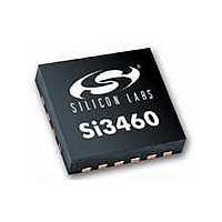
SI3460-E02-GM Silicon Laboratories Inc, SI3460-E02-GM Datasheet - Page 6

SI3460-E02-GM
Manufacturer Part Number
SI3460-E02-GM
Description
IC POWER MANAGEMENT CTLR 11VQFN
Manufacturer
Silicon Laboratories Inc
Datasheet
1.SI3460-E02-GMR.pdf
(24 pages)
Specifications of SI3460-E02-GM
Package / Case
11-VQFN
Applications
Power Sourcing Equipment (PSE)
Current - Supply
500mA
Voltage - Supply
2.7 V ~ 3.6 V
Operating Temperature
-40°C ~ 85°C
Mounting Type
Surface Mount
Product
PoE / LAN Solutions
Supply Voltage (max)
16 V
Supply Voltage (min)
11 V
Operating Temperature Range
- 40 C to + 85 C
Mounting Style
SMD/SMT
Lead Free Status / RoHS Status
Lead free / RoHS Compliant
Lead Free Status / RoHS Status
Lead free / RoHS Compliant, Lead free / RoHS Compliant
Available stocks
Company
Part Number
Manufacturer
Quantity
Price
Company:
Part Number:
SI3460-E02-GM
Manufacturer:
Silicon Labs
Quantity:
135
Company:
Part Number:
SI3460-E02-GMR
Manufacturer:
SILICON
Quantity:
1 001
Si3460
2. Si3460 Electrical Specifications
The following specifications apply to the Si3460 controller. Refer to Tables 1, 5, 6, and 7, the Si3460-EVB User’s
Guide, and schematics for additional details about the electrical specifications of the Si3460-EVB reference design.
Table 2. Recommended Operating Conditions*
Table 3. Absolute Maximum Ratings*
6
Description
Operating temperature range
Thermal impedance
VDD input supply voltage
*Note: VDD = 2.7 to 3.6 V, –40 to +85 °C unless otherwise specified.
Parameter
Ambient temperature under bias
Storage Temperature
Voltage on RST or any I/O pin with respect to GND
Voltage on VDD with respect to GND
Maximum total current through VDD
and GND
Maximum output current into GATE, CTRL1,
CTRL2, 250KHZ, STATUS, ISENSE, RST,
VSENSE, DETA (any I/O pin)
ESD tolerance
Lead Temperature
*Note: Stresses above those listed in this table may cause permanent device damage. This is a stress rating only, and
functional operation of the devices at these or any conditions above those indicated in the operational listings of this
specification is not implied. Exposure to maximum rating conditions for extended periods may affect device reliability.
Symbol
VDD
T
JA
A
(detect, classification, disconnect)
During all operating modes
Rev. 1.1
Soldering, 10 seconds maximum
Test Conditions
No airflow
Human Body Model
VDD > 2.2 V
Conditions
Min
–40
2.7
—
–2 kV to +2 kV
Max Rating
–55 to +125
–65 to +150
–0.3 to 5.8
–0.3 to 4.2
Typ
3.3
25
75
500
100
260
Max
+85
3.6
—
°C/W
Unit
Unit
mA
mA
°C
°C
°C
°C
V
V
V
V


