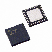
LTC1923EUH Linear Technology, LTC1923EUH Datasheet - Page 13

LTC1923EUH
Manufacturer Part Number
LTC1923EUH
Description
IC THERMOELEC COOLER CNTRLR32QFN
Manufacturer
Linear Technology
Datasheet
1.LTC1923EGN.pdf
(28 pages)
Specifications of LTC1923EUH
Applications
Thermoelectric Cooler/Heater
Current - Supply
2mA
Voltage - Supply
2.7 V ~ 5.5 V
Operating Temperature
-40°C ~ 85°C
Mounting Type
Surface Mount
Package / Case
32-QFN
Lead Free Status / RoHS Status
Contains lead / RoHS non-compliant
Available stocks
Company
Part Number
Manufacturer
Quantity
Price
Company:
Part Number:
LTC1923EUH
Manufacturer:
LT
Quantity:
10 000
Part Number:
LTC1923EUH
Manufacturer:
LT
Quantity:
20 000
Company:
Part Number:
LTC1923EUH#PBF
Manufacturer:
LINEAR
Quantity:
35
Part Number:
LTC1923EUH#PBF
Manufacturer:
LINEAR/凌特
Quantity:
20 000
Company:
Part Number:
LTC1923EUH#TRPB
Manufacturer:
LINEAR
Quantity:
719
Company:
Part Number:
LTC1923EUH#TRPBF
Manufacturer:
MICRON
Quantity:
38
Company:
Part Number:
LTC1923EUHTRPBF
Manufacturer:
CONEXANT
Quantity:
63
OPERATIO
Transistor M1 is off and the current limit threshold is given
by:
When TEC
H/C, pulls high through R
The current limit value is given by:
reducing the current limit threshold for heating. If the
heating current limit needs to be greater than the cooling
limit, an extra inversion can be added.
Open/Shorted Thermistor Detection
The temperature sense element (NTC thermistor, plati-
num RTD or other appropriate component) must be prop-
erly connected in order for the system to regulate
temperature. If the sense element is incorrectly con-
nected, the system will be unable to control the tempera-
ture and the potential exists for the system to thermally run
away.
A TEC by nature produces a temperature differential be-
tween opposite sides of the device depending upon how
much current is flowing through it. There is a maximum
limit to the amount of temperature differential that can be
produced, which depends upon a number of physical
I
I
LIMIT
LIMIT
Figure 4. Independently Heating/Cooling Current Limit
V
REF
R
R
2N7002
ILIM2
ILIM1
M1
–
0 15
R
is greater than TEC
R
0 15
.
R
ILIM
ILIM
.
LIM3
•
U
1
2
•
V
R
R
DD
R
ILIM
ILIM
R
R
PULLUP
ILIM
ILIM
1
1
PULLUP
I
H/C
•
R
LIM
2
1
V
ILIM
R
REF
•
ILIM
R
3
+
S
, causing M1 to turn on.
, the open-drain output,
3
•
LTC1923
V
•
REF
R
S
+
–
TEC
TEC
1923 F04
+
–
parameters including the size of the TEC and how well
heatsinked the device is. The TEC itself dissipates power
to produce the temperature differential, generating heat,
which must also be removed. At a certain level of power
dissipation in the TEC, both sides will begin to heat. This
is because the TEC will not be able to pump the self-
generated heat to the outside world, which can lead to
thermal runaway. If the device thermally runs away, dam-
age to the TEC and possibly the components whose
temperature is being regulated will occur.
The LTC1923 contains two dedicated comparators that
directly monitor the voltage on the thermistor. If this
voltage is outside the valid window, a latch is set and the
FAULT pin is asserted low. The output drivers are not shut
off and the control circuitry is not disabled, meaning the
part will continue to try to regulate temperature. It is up to
the user to use the FAULT signal to disable the appropriate
circuitry. There are a couple of ways to do this. The first
way is to have the FAULT signal a system microprocessor
to shut the system down through the SDSYNC pin. Fig-
ure 5 shows another means of protecting the system.
External NMOS M1 and PMOS M2 have been added along
with two pull-up resistors (RP1 and RP2). M1 and RP2
invert the FAULT signal while M2 acts as a switch in series
with bridge. When no fault is present, the gate of M1 is
FAULT
V
DD
PDRVB
NDRVB
NDRVA
PDRVA
R
CS
CS
P1
Figure 5. Redundant Fault Protection
+
–
V
DD
M1
R
P2
3
4
1
2
R
S
V
TEC
DD
M2
LTC1923
1923 F05
13
1923f


