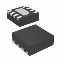
ISL21440IRTZ Intersil, ISL21440IRTZ Datasheet - Page 12

ISL21440IRTZ
Manufacturer Part Number
ISL21440IRTZ
Description
IC VREF W/COMPARATOR 8TDFN
Manufacturer
Intersil
Series
FGA™r
Datasheet
1.ISL21440IRTZ.pdf
(16 pages)
Specifications of ISL21440IRTZ
Applications
Comparator, Voltage Reference
Current - Supply
460µA
Voltage - Supply
2 V ~ 11 V
Operating Temperature
-40°C ~ 125°C
Mounting Type
Surface Mount
Package / Case
*
Rohs Compliant
Yes
Lead Free Status / RoHS Status
Lead free / RoHS Compliant
Available stocks
Company
Part Number
Manufacturer
Quantity
Price
Part Number:
ISL21440IRTZ
Manufacturer:
INTERSIL
Quantity:
20 000
10mV or more under extreme radiation. If an assembled board
needs to be X-rayed, care should be taken to shield the FGA
reference device.
Hysteresis
The Hysteresis function allows for changing the value of the
reference switchover point depending on the previous state of
the comparator. This works to remove the effects of noise or
glitches in the voltage detection input and provide more reliable
output transitions.
Hysteresis is added to the ISL21440 by connecting one resistor
between the REF and HYST pins (R
resistor(R
voltage (V
between the HYST pin and REF pin (V
Since the reference voltage is 1.182V (V
for these two resistors are shown as follows:
I
reference, usually 5µA is a safe value but for lowest power, 0.1µA
can be used.
If the hysteresis is not used, the HYST pin should be tied to the
REF pin.
Board Assembly Considerations
FGA references provide high accuracy and low temperature drift
but some PC board assembly precautions are necessary. Normal
Output voltage shifts of 100µV to 1mV can be expected with
Pb-free reflow profiles or wave solder on multi-layer FR4 PC
boards. Precautions should be taken to avoid excessive heat or
extended exposure to high reflow or wave solder temperatures,
this may reduce device initial accuracy.
Post-assembly X-ray inspection may also lead to permanent
changes in device output voltage and should be minimized or
avoided. If X-ray inspection is required, it is advisable to monitor
the reference output voltage to verify excessive shift has not
occurred. If large amounts of shift are observed, it is best to add
an X-ray shield consisting of thin zinc (300µm) sheeting to allow
clear imaging, yet block x-ray energy that affects the FGA
reference.
Special Applications Considerations
In addition to post-assembly examination, there are also other
X-ray sources that may affect the FGA reference long term
accuracy. Airport screening machines contain X-rays and will
have a cumulative effect on the voltage reference output
accuracy. Carry-on luggage screening uses low level X-rays and is
not a major source of output voltage shift, although if a product
is expected to pass through that type of screening over 100x it
may need to consider shielding with copper or aluminum.
Checked luggage X-rays are higher intensity and can cause
output voltage shift in much fewer passes, so devices expected to
go through those machines should definitely consider shielding.
Note that just two layers of 1/2 ounce copper planes will reduce
R
R
REF
REF
HYST
is chosen to be less than the maximum output of the
=
=
V
H
(
HYST
H
1.182 V
) is designed to be twice the voltage difference
⁄
(
2 ∗ I
) between the HYST pin and ground. The hysteresis
REF
–
H
)
2 ⁄
=
) I
(
⁄
V
REF
REF
–
12
=
V
HYST
V
HYST
REF
) I
H
⁄
), and another
⁄
= 2 * (V
I
REF
REF
REF
), Equations 1 and 2
REF
- V
HYST
ISL21440
)).
(EQ. 1)
(EQ. 2)
the received dose by over 90%. The lead frame for the device
which is on the bottom also provides similar shielding.
If a device is expected to pass through luggage X-ray machines
numerous times, it is advised to mount a 2-layer (minimum) PC
board over the top of the package, which along with a ground
plane underneath will effectively shield it from 50 to 100 passes
through the machine. Since these machines vary in X-ray dose
delivered, it is difficult to produce an accurate maximum pass
recommendation.
Typical Applications
Low Battery Detector
Figure 26 shows a typical implementation for the ISL21440, a
low battery detector. The values for R
20mV of hysteresis and 0.5µA I
V
resistor divider at the input sets the Lo
total current draw for the circuit is going to be 1.1µA for V
0.6µA for V
Window Comparator
The ISL21440 can be combined with a micropower comparator
to produce a window comparator circuit. The circuit in Figure 27
uses a 3 resistor divider to produce high and low trip points, and
the ISL28197 (800nA supply current) comparator is added to
give the second output. The two outputs can be used separately
for over or undervoltage indication, or a gate can be added as
shown to report either in-window or out-of window condition.
The resistors are shown as Equations 3, 4 and 5 as follows.
Set:
Example: For V
R
The resulting circuit draws about 3µA and works down to V
2.2V.
R
R
R
detect
2
3
2
1
FIGURE 26. LOW BATTERY DETECTOR WITH HYSTERESIS
= 402k, R
=
=
=
1M 1%
R
R
is the same as the reference voltage, 1.182V, and a
3
3
V
[
(
BAT
(
V
[
V
1.8M
H
2.4M
BAT
H
⁄
)
V
⁄
1
V
L
.
H
20k
2.4M
= 1.82M (can be 1%)
REF
–
= 3.8V, V
1
]
–
1
] R
–
L
2
HYST
REF
= 2.7V (3.3V ± 0.5V)
IN+
)
IN-
REF
+
-
V
. The input trip point for
DD
ISL21440
V-
REF
BAT
V+
and R
GND
trip point at 2.7V. The
OUT
HYST
February 23, 2011
Lo
provide
BAT
-
FN6532.2
DD
(EQ. 3)
(EQ. 4)
(EQ. 5)
DD
and
=


