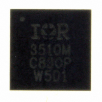
IR3510MTRPBF International Rectifier, IR3510MTRPBF Datasheet - Page 10

IR3510MTRPBF
Manufacturer Part Number
IR3510MTRPBF
Description
IC XPHASE CONTROL 32-MLPQ
Manufacturer
International Rectifier
Series
XPhase™r
Datasheet
1.IR3510MTRPBF.pdf
(36 pages)
Specifications of IR3510MTRPBF
Applications
Processor
Mounting Type
Surface Mount
Package / Case
32-MLPQ
Package
32-Lead MLPQ
Circuit
X-Phase Control IC
Pbf
PbF Option Available
Lead Free Status / RoHS Status
Lead free / RoHS Compliant
Current - Supply
-
Voltage - Supply
-
Operating Temperature
-
Other names
IR3510MTRPBFTR
Available stocks
Company
Part Number
Manufacturer
Quantity
Price
Part Number:
IR3510MTRPBF
Manufacturer:
IR
Quantity:
20 000
IR3510
PIN FUNCTIONS
“VCC” (PIN#1): 12V bias voltage input for internal circuit. Connecting a 1uF decoupling cap is recommended.
“CX” (PIN#2): Charge-pump output. It is internally clamped to 27V typical and 29V max. Connecting a 0.1uF /
50V cap to GND is required.
“Enable” (PIN#3): Input FET and voltage regulator output enable input. It has two-level threshold. The lower level
threshold of 0.7V turns on the input FET. The higher level threshold of 1.2V turns on the voltage regulator output. It
has internal pull-up to 0.9V, so when it is float, it has the voltage above the lower level threshold and turns on input
FET. When it is pulled down, both input FET and voltage regulator output are turned off.
“VRRDY” (PIN#4): Open collector output indicating that the soft-start is completed and there is no fault. It requires
external pull-up.
“ORING” (PIN#5): Open collector output indicating Oring FET status. It requires external pull-up. HIGH indicates
the Oring FET is ON; LOW indicates the Oring FET is OFF.
“VSET” (PIN#6): Analog input setting the no-load output voltage. It is internally connected to the non-inverting
input of voltage error amplifier.
“OVPSET” (PIN#7): Analog input setting the Over-Voltage Protection threshold voltage. The internal OVP circuit
compares the voltage on the “OVPS” pin and the voltage on this pin to determine the OV condition.
“OCPSET” (PIN#8): Analog input setting the constant current limit. The internal constant current limit circuit limits
the “IO” pin voltage, which is the current report voltage, to be no more than the voltage set on this pin.
“SS” (PIN#9): Soft-start pin. Connect a capacitor to GND to set the soft-start time. An internal current source
flowing out of this pin charges the cap to a fixed threshold to set the soft-start time. It controls both the input FET
soft-start and the voltage regulator output voltage soft-start.
“IOCD” (PIN#10): Input FET fault indication output. Connect a capacitor to GND to program the input OCP delay
time. Any fault condition which results turning off the input FET, including input FET short, input OCP and output
OVP, will cause this pin be pulled HIGH.
“VOSNS-” (PIN#11): Negative remote sense input. It is internally connected to the inverting input of the differential
voltage sense amplifier.
“VOSNS+” (PIN#12): Positive remote sense input. It is internally connected to the non-inverting input of the
differential voltage sense amplifier.
“OVPSNS” (PIN#13): OVP sense input. It can be connected to “VO” pin if there is no feedback divider. If the
output voltage is higher than the “VSET” voltage, a feedback resistor divider is required, and this pin needs to be
connected to “VFB” pin. To disable internal OVP function, connecting this pin to GND.
“VO” (PIN#14): Remote sense voltage output. If the output voltage is higher than the “VSET” voltage, a feedback
resistor divider is required to be connected to this pin.
IR Confidential
Page 10 of 36
May 18, 2009


