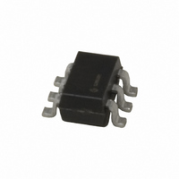
MIC2015-1.2YM6 TR Micrel Inc, MIC2015-1.2YM6 TR Datasheet

MIC2015-1.2YM6 TR
Specifications of MIC2015-1.2YM6 TR
MIC2015-1.2YM6 TR
MIC2015-1.2YM6TR
MIC2015-1.2YM6TR
Related parts for MIC2015-1.2YM6 TR
MIC2015-1.2YM6 TR Summary of contents
Page 1
... The FET is self-contained, with the current limit value being factory set to one of several convenient levels. MIC2015 offers a unique new patented feature: ™ Kickstart , which allows momentary high current surges to pass unrestricted without sacrificing overall system safety ...
Page 2
... Ordering Information Part Number MIC2005-0.5YM5 MIC2005-0.8YM5 MIC2005-1.2YM5 MIC2005-0.5YM6 MIC2005-0.8YM6 MIC2005-1.2YM6 MIC2005-0.5YML MIC2005-0.8YML MIC2005-1.2YML MIC2015-0.5YM6 MIC2015-0.8YM6 MIC2015-1.2YM6 MIC2015-0.5YML MIC2015-0.8YML MIC2015-1.2YML Notes: 1. All MIC2005/2015 parts are lead free. 2. Under-bar symbol ( _ ) may not be to scale January 2008 4 I Adj. Enable C I Limit -- -- -- ▲ Fixed -- ▲ ...
Page 3
Micrel Pin Configuration OUT NIC GND NIC ENABLE 3 4 6-Lead 2 ...
Page 4
... MLF 2x2 mm θ Conditions Switch = OFF, ENABLE = 0V Switch = ON OUT ENABLE = 1. 5V ENABLE IN OUT = 5V 100 mA IN OUT OUT IN OUT OUT IN OUT OUT IN OUT MIC2015 2. Rising IN V Falling IN V (max (min 5. 10mA OL T increasing J T decreasing (5) .................................. JC Min Typ 2 ...
Page 5
... L LOAD 500 V = 10% to 90% OUT Time from current limiting to FAULT/ state change. MIC2005 Time from I continuously OUT exceeding primary current limit condition to FAULT/ state change. MIC2015 MIC2015 Out of current limit following a current limit. MIC2015 R = 43Ω 120µ 50 90% EN OUT R = 43Ω ...
Page 6
Timing Diagrams ENABLE VOUT January 2008 50% t ON_DLY 90% Switching Delay Times t RISE 90% 90% 10% 10% Rise and Fall Times t RISE 90% VOUT 10% Output Rise Time 6 50% t OFF_DLY 10% t FALL M9999-011708-A (408) ...
Page 7
Typical Characteristics Supply Current Output Enabled 100 25°C -40°C 80 85° ( vs. Temperature LIMIT (MIC20xx-1.2) 1. 2.5V 1. 1.50 1.45 ...
Page 8
Functional Characteristics January 2008 8 M9999-011708-A (408) 944-0800 ...
Page 9
January 2008 9 M9999-011708-A (408) 944-0800 ...
Page 10
Functional Diagram ...
Page 11
... If the load demands a current in excess the secondary limit, MIC2015 acts immediately to restrict output current to the secondary limit for the January 2008 duration of the Kickstart period. After this time the MIC2015 reverts to its normal current limit. An example of Kickstart operation is shown below. is the OUT is greater than V ...
Page 12
ENABLE ENABLE is a HIGH or LOW true control signal, which activates the main MOSFET switch. ENABLE has two voltage ranges depending on whether the switch is an active high or active low device.. ENABLE can be wire- OR’d with ...
Page 13
Application Information I vs. I measured LIMIT OUT MIC2005/2015’s current limiting circuitry is designed to act as a constant current source to the load. As the load tries to pull more than the allotted current, V and the input to ...
Page 14
... During Kickstart a secondary current limiting circuit is monitoring output current to prevent damage to the MIC2015 hard short combined with a robust power supply can result in currents of many tens of amperes. This secondary current limit is nominally set at 4 Amps and reacts immediately and independently of the Kickstart period ...
Page 15
Supply Filtering A 0.1µF to 1µF bypass capacitor positioned close to the V and GND pins of MIC2005/2015 is both good design IN practice and required for MIC2005/2015. This will control supply transients and ringing. Without a bypass capacitor, large ...
Page 16
Package Information January 2008 2 Vias 0.3 mm diam. to Ground Plane 0.8 mm Figure 11. Pad for thermal mounting to PCB 6-Pin SOT-23 (M6) 16 1.4 mm M9999-011708-A (408) 944-0800 ...
Page 17
Package Information (Cont.) 1.90 (0.075) REF 0.95 (0.037) REF January 2008 1.75 (0.069) 3.00 (0.118) 1.50 (0.059) 2.60 (0.102) 1.30 (0.051) 3.02 (0.119) 0.90 (0.035) 2.80 (0.110) 0.15 (0.006) 0.50 (0.020) 0.00 (0.000) 0.35 (0.014) 5-Pin SOT-23 (M5) 6 Pin ...
Page 18
MICREL, INC. 2180 FORTUNE DRIVE SAN JOSE, CA 95131 USA TEL +1 (408) 944-0800 FAX +1 (408) 474-1000 WEB http:/www.micrel.com The information furnished by Micrel in this data sheet is believed to be accurate and reliable. However, no responsibility is ...


