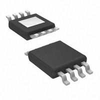
AP2145MPG-13 Diodes Inc, AP2145MPG-13 Datasheet - Page 9

AP2145MPG-13
Manufacturer Part Number
AP2145MPG-13
Description
IC SINGLE USB SWITCH 800MA 8MSOP
Manufacturer
Diodes Inc
Type
USB Switchr
Datasheet
1.AP2145SG-13.pdf
(13 pages)
Specifications of AP2145MPG-13
Number Of Outputs
1
Rds (on)
140 mOhm
Internal Switch(s)
Yes
Current Limit
800mA
Voltage - Input
2.7 ~ 5.5 V
Operating Temperature
-40°C ~ 85°C
Mounting Type
Surface Mount
Package / Case
8-MSOP Exposed Pad, 8-HMSOP, 8-eMSOP
Lead Free Status / RoHS Status
Lead free / RoHS Compliant
Other names
AP2145MPG-13TR
Available stocks
Company
Part Number
Manufacturer
Quantity
Price
Part Number:
AP2145MPG-13
Manufacturer:
DIODES/美台
Quantity:
20 000
Application Note
Power Supply Considerations
A 0.1-μF to 1-μF X7R or X5R ceramic bypass capacitor
between
recommended. Placing a high-value electrolytic capacitor
on the input and output pin(s) is recommended when the
output load is heavy. This precaution reduces power-
supply transients that may cause ringing on the input.
Additionally, bypassing the output with a 0.01-μF to 0.1-μF
ceramic capacitor improves the immunity of the device to
short-circuit transients.
Over-current and Short Circuit Protection
An internal sensing FET is employed to check for over-
current conditions. Unlike current-sense resistors, sense
FETs do not increase the series resistance of the current
path. When an overcurrent condition is detected, the
device maintains a constant output current and reduces
the output voltage accordingly. Complete shutdown occurs
only if the fault stays long enough to activate thermal
limiting.
Three possible overload conditions can occur. In the first
condition, the output has been shorted to GND before the
device is enabled or before VIN has been applied. The
AP2145/AP2155 senses the short circuit and immediately
clamps output current to a certain safe level namely I
In the second condition, an output short or an overload
occurs while the device is enabled. At the instance the
overload occurs, higher current may flow for a very short
period of time before the current limit function can react.
After the current limit function has tripped (reached the
over-current trip threshold), the device switches into
current limiting mode and the current is clamped at I
In the third condition, the load has been gradually
increased beyond the recommended operating current.
The current is permitted to rise until the current-limit
threshold (I
device is exceeded. The AP2145/AP2155 is capable of
delivering current up to the current-limit threshold without
damaging the device. Once the threshold has been
reached, the device switches into its current limiting mode
and is set at I
To protect against short circuit to GND at extremely low
temperature (< -30
capacitor on the output pin is recommended. A correct
capacitor
temperature characteristics must be properly chosen so
that capacitance value does not drop too low at the
AP2145/AP2155
Document number: DS32031 Rev. 2 - 2
IN
TRIG
type
LIMIT
) is reached or until the thermal limit of the
and
.
with
o
C), a minimum 120-μF electrolytic
GND,
capacitor
close
voltage
to
the
rating
device,
0.5A SINGLE CHANNEL CURRENT-LIMITED POWER
LIMIT
LIMIT
and
www.diodes.com
.
.
is
9 of 13
extremely low temperature operation. A recommended
capacitor should have temperature characteristics of less
than 10% variation of capacitance change when operated
at extremely low temp. Our recommended aluminum
electrolytic capacitor type is Panasonic FC series.
FLG Response
When an over-current or over-temperature shutdown
condition is encountered, the FLG open-drain output
goes active low after a nominal 7-ms deglitch timeout.
The FLG output remains low until both over-current and
over-temperature conditions are removed. Connecting a
heavy capacitive load to the output of the device can
cause a momentary over-current condition, which does
not trigger the FLG due to the 7-ms deglitch timeout. The
AP2145/AP2155 is designed to eliminate false over-
current
components to remove unwanted pulses.
Power Dissipation and Junction Temperature
The low on-resistance of the internal MOSFET allows the
small surface-mount packages to pass large current.
Using the maximum operating ambient temperature (TA)
and RDS(ON), the power dissipation can be calculated
by:
Finally, calculate the junction temperature:
Where:
Thermal Protection
Thermal protection prevents the IC from damage when
heavy-overload or short-circuit faults are present for
extended
implements a thermal sensing to monitor the operating
junction temperature of the power distribution switch.
Once the die temperature rises to approximately 140°C
due to excessive power dissipation in an over-current or
short-circuit condition the internal thermal sense circuitry
turns the power switch off, thus preventing the power
switch from damage. Hysteresis is built into the thermal
sense circuit allowing the device to cool down
approximately 25°C before the switch turns back on. The
switch continues to cycle in this manner until the load
fault or input power is removed. The FLG open-drain
output is asserted when an over-temperature shutdown
or over-current occurs with 7-ms deglitch.
SWITCH WITH OUTPUT DISCHARGE
P
T
T
R
P
J
A
D
θ JA
D
= Ambient temperature °C
= P
= R
= Total power dissipation
reporting
= Thermal resistance
periods
D
DS(ON)
x R
θ JA
× I
AP2145/AP2155
+ T
2
without
of
A
time.
the
The
need
AP2145/AP2155
© Diodes Incorporated
September 2010
of
external


