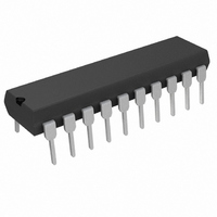
LT1508CN Linear Technology, LT1508CN Datasheet - Page 12

LT1508CN
Manufacturer Part Number
LT1508CN
Description
IC PWM/POWER FACTOR CNTRLR 20DIP
Manufacturer
Linear Technology
Datasheet
1.LT1508CSW.pdf
(16 pages)
Specifications of LT1508CN
Mode
Average Current
Frequency - Switching
100kHz
Voltage - Supply
27V
Operating Temperature
0°C ~ 100°C
Mounting Type
Through Hole
Package / Case
20-DIP (0.300", 7.62mm)
Lead Free Status / RoHS Status
Contains lead / RoHS non-compliant
Current - Startup
-
12
LT1508
APPLICATIONS
The total equivalent 120Hz ripple in the output capacitor
can be calculated by:
I
For I
120Hz ripple current is:
Table 1 lists the ripple current components from lab
measurements for various output powers and line volt-
ages. The 120Hz ripple current rating at 105 C ambient is
1.72A for the 470 F KMH 35mm 50mm capacitor. The
expected life of the output capacitor may be calculated
from thermal stress analysis:
where
L = Expected life time
L
ambient temperature
condition. T
rent, R is capacitor ESR and KA is a volume constant.
T
condition
HF
O
A
T
T
I
I
L = (L
K
O
= Operating ambient temperature
= Hours of load life at rated ripple current and rated
RMS
= 100kHz Ripple Current.
RMS
LOAD(DC)
= Capacitor internal temperature rise at rated
= Capacitor internal temperature rise at operating
=
=
O
)2
I
0.62
(105 C + T
K
= 0.88A, 1
120HZ
= (I
2
2
U
+
R)/(KA), where I is the rated cur-
2
+
1.79
1.43
120Hz
1.43
K
10
I
INFORMATION
) – (T
HF
U
2
2
= 0.62A and the equivalent
A
= 1.4A
+ T
W
O
)
RMS
U
Table 1. PFC Capacitor RMS Ripple Current
In our example, L
rated 1.72A. T
Assuming the operating ambient temperature is 60 C, the
approximate lifetime is:
For longer life a capacitor with a higher ripple current rating
or parallel capacitors should be used.
PWM Comparators
The LT1508 includes two comparators in the PWM section
which implement voltage mode PWM control. The V
control voltage pin sets duty factor. An additional current
limit comparator turns GTDR2 off in the event the I
voltage exceeds 1.1V. On-chip blanking avoids reset due
to leading edge noise.
Typical Application
Figure 9 shows a 24VDC, 300W power factor corrected,
universal input supply. The 2-transistor forward converter
offers many benefits including low peak currents,
nondissipative snubber, 500VDC switches and automatic
core reset guaranteed by the LT1508’s 50% maximum
duty cycle.
V
INRMS
100
120
230
L = (2000)(2)
= 50,870 Hours
T
O
= T
I
120HZ
0.2
0.2
0.2
K
100W
1.72A
O
I
RMS
O
can then be calculated from:
0.53
(105 C + 5 C) – (60 + 3.3 C)
0.6
0.5
I
HF
= 2000 hours assuming T
2
= 5 C
I
120HZ
0.41
0.41
0.41
10
200W
1.72A
1.4A
1.18
0.97
0.87
I
HF
2
= 3.3 C
I
120HZ
0.62
0.62
0.62
300W
K
= 5 C at
LIM
1.79
1.45
1.26
I
HF
C
pin
or


