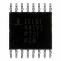
ISL6144IVZA Intersil, ISL6144IVZA Datasheet - Page 21

ISL6144IVZA
Manufacturer Part Number
ISL6144IVZA
Description
IC CTRLR MOSFET ORING HV 16TSSOP
Manufacturer
Intersil
Datasheet
1.ISL6144IVZA.pdf
(29 pages)
Specifications of ISL6144IVZA
Applications
Telecom/Datacom Systems
Fet Type
N-Channel
Number Of Outputs
1
Internal Switch(s)
No
Delay Time - On
1ms
Delay Time - Off
250ns
Voltage - Supply
10 V ~ 75 V
Operating Temperature
-40°C ~ 105°C
Mounting Type
Surface Mount
Package / Case
16-TSSOP
Lead Free Status / RoHS Status
Lead free / RoHS Compliant
Current - Supply
-
Available stocks
Company
Part Number
Manufacturer
Quantity
Price
Company:
Part Number:
ISL6144IVZA
Manufacturer:
Intersil
Quantity:
304
Part Number:
ISL6144IVZA
Manufacturer:
INTERSIL
Quantity:
20 000
Company:
Part Number:
ISL6144IVZA-T
Manufacturer:
ST
Quantity:
3 200
Fault 6: ORing FET Body Diode Conduction
(V
MOSFET approaches 410mV, a fault will be indicated. Make
sure the selection of the ORing MOSFET takes this fact into
account.
Application Considerations and
Component Selection
“ISL6144 + ORing FET” vs “ORing Diode” Solution
“ISL6144 + ORing FET“ solution is more efficient than the
“ORing Diode” Solution, which will result in simplified PCB
and thermal design. It will also eliminate the need for a heat
sink for the ORing diode. This will result in cost savings. In
addition is the fact that the ISL6144 solution provides a more
flexible, reliable and controllable ORing functionality and
protects against system fault scenarios (Refer to the “Fault
Detection Block” on page 8.)
On the other hand the most common failures caused by
diode ORing include open circuit and short circuit failures. If
one of these diodes (Feed A) has failed open, then the other
Feed B will provide all of the power demand. The system will
continue to operate without any notification of this failure,
reducing the system to a single point of failure. A much more
dangerous failure is where the diode has failed short. The
system will continue to operate without notification that the
short has occurred. With this failure, transients and failures
on Feed B propagate to Feed A. Also, this silent short failure
could pose a significant safety hazard for technical
personnel servicing these feeds.
“ISL6144 + ORing FET” vs “Discrete ORing FET”
Solution
If we compare the ISL6144 integrated solution to discrete
ORing MOSFET solutions (with similar performance
parameters), the ISL6144 wins in all aspects, the main ones
being simplicity of an integrated solution, PCB real estate
saving, cost savings, and reduction in the MTBF of this section
of the circuit as the overall number of components is reduced.
In brief, the solution offered by this IC enhances power
system performance and protection while not adding any
considerable cost, on the contrary saving PCB board real
estate and providing a simple to implement integrated
solution.
ORing MOSFET Selection
Using an ORing MOSFET instead of an ORing diode results
in increased overall power system efficiency as losses across
the ORing elements are reduced. The benefit of using ORing
MOSFETs becomes even more significant at higher load
currents as power loss and forward voltage drop across the
traditionally used ORing diode is increased. The high power
dissipation across these diodes requires paralleling of many
diodes as well as special thermal design precautions such as
heat sinks (heat dissipating pads) and forced airflow.
IN
- 0.41V > V
OUT
). If the voltage drop across the
21
ISL6144
For example, in a 48V, 32A (1 + 1) redundant system with
current sharing, using a Schottky diode as the ORing device
(Refer to Figure 29), the forward voltage drop is in the 0.4V to
0.7V range, (let us assume it is 0.5V). The power loss across
each diode is shown in Equation 10:
The total power loss across the two ORing diodes is 16W.
If we use a 4.5mΩ MOSFET (refer to Figure 30), the nominal
Power loss across each MOSFET is:
The total power loss across the two ORing MOSFETs is
2.304W.
In case of failure of current sharing scheme, or failure of
DC/DC 1, the full load will be supplied by DC/DC 2. ORing
MOSFET M2 or ORing Diode D
load current. Power lost across the ORing devices are:
P loss D1
P loss
P loss
P loss
P loss
FIGURE 30. 1+1 REDUNDANT SYSTEM WITH MOSFET ORING
FIGURE 29. 1 + 1 REDUNDANT SYSTEM WITH DIODE ORING
INPUT BUS 1
INPUT BUS 1
INPUT BUS 2
INPUT BUS 2
(
(
NOM M
MAX
MAX M2
M
1
)
)
(
(
(
=
D
=
2
1
P loss D2
P loss
)
)
)
=
=
=
CS
I OUT V F
(
(
I OUT
DC/DC
DC/DC
DC/DC
(
16A
DC/DC
(
M
1
2
1
2
2
CS
)
)
)
⋅
2
)
=
=
2
⋅
4.5mΩ
⋅
I OUT
-------------- - V
⎛
⎝
r
I OUT
-------------- -
+IN1 = 48V
DS ON
+IN2 = 48V
=
+IN1 = 48V
+IN2 = 48V
2
2
32A 0.5V
(
2
⋅
⎞
⎠
=
will be conducting the full
2
)
⋅
F
⋅
1.152W
=
r
=
DS ON
(
32A
16A 0.5V
0.072V @ 16A
0.072V@ 16A
(
=
0.5V @ 16A
)
4.5mΩ
16W
4.5mΩ
2
⋅
)
0.5V@ 16A
M2
M1
⋅
4.5mΩ
D
D
2
1
January 6, 2011
=
8W
(EQ. 12)
(EQ. 13)
(EQ. 10)
(EQ. 11)
=
V
(32A)
V
FN9131.6
(32A)
OUT
OUT
4.6W


