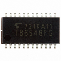
TB6548FG Toshiba, TB6548FG Datasheet - Page 4

TB6548FG
Manufacturer Part Number
TB6548FG
Description
IC CTLR SENSORLESS 3PHASE 24SSOP
Manufacturer
Toshiba
Type
3 Phase Sensorless Motor Driverr
Datasheet
1.TB6548FG.pdf
(14 pages)
Specifications of TB6548FG
Applications
DC Motor Controller, Brushless (BLDC), 3 Phase
Number Of Outputs
1
Voltage - Supply
4.5 V ~ 5.5 V
Operating Temperature
-30°C ~ 85°C
Mounting Type
Surface Mount
Package / Case
24-SSOP
Operating Supply Voltage
5 V
Supply Current
0.3 mA
Mounting Style
SMD/SMT
Lead Free Status / RoHS Status
Lead free / RoHS Compliant
Current - Output
-
Voltage - Load
-
Lead Free Status / Rohs Status
Lead free / RoHS Compliant
Functional Description
1. Sensorless Drive
2. Starting Commutation Frequency
3. PWM Control
Pin No.
21
22
23
24
(commutation irrespective of the rotor position of the motor) is output and the motor starts to rotate. The
rotation of the motor causes induced voltage on the wirewound pin for each phase.
are input through their respective positional signal input pins, the turn-on signal for forcible commutation
is automatically switched to the turn-on signal for the positional signal (induced voltage).
as to drive the brushless DC motor.
the number of counter bits (within the IC).
and the load.
sources.
the motor and in accordance with the switching characteristics of the drive circuit.
positional detection cannot be performed with 0% duty or 100% duty.
the drive circuit.
Starting commutation frequency f
On receipt of the start instruction by PWM signal, the turn-in signal for forcible commutation
When signals indicating positive or negative for pin voltage (including induced voltage) for each phase
Thereafter, the turn-on signal is formed according to the induced voltage contained in the pin voltage so
The forcible commutation frequency at the time of start is determined by the resonator’s frequency and
The forcible commutation frequency at the time of start can be adjusted using the inertia of the motor
The PWM signal can be reflected in the turn-on signal by supplying the PWM signal from external
The frequency of the PWM signal should be set adequately high with regard to the electrical frequency of
Because positional detection is performed in synchronization with the falling edges of the PWM signal,
Even if the duty is 99%, the duty of the voltage applied to the motor is 100% owing to the storage time of
• The forcible commutation frequency should be set higher as the number of magnetic poles increases.
• The forcible commutation frequency should be set lower as the inertia of the load increases.
OUT_WP
OUT_WN
Symbol
WAVE
OC
Duty (min)
Duty (max)
I/O
O
O
I
I
W-phase upper turn-on signal output pin
•
•
W-phase lower turn-on signal output pin
•
•
Overcurrent signal input pin
•
•
Positional signal input pin
•
•
W-phase winding wire positive ON/OFF switching pin
ON: Low, OFF: High
W-phase winding wire negative ON/OFF switching pin
ON: High, OFF: Low
High on this pin can put constraints on the turn-on signal performing PWM control.
Built-in pull-up resistor
Inputs majority logic synthesis signal of three-phase pin voltage.
Built-in pull-up resistor
st
= Resonator frequency f
(resonator pin and counter bit select pin)
4
xt
Description
/(6 × 2
250 ns
250 ns
(bit + 3)
)
bits = 14
TB6548F/FG
2006-03-02


