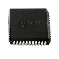
UDQ2916EB Allegro Microsystems Inc, UDQ2916EB Datasheet - Page 9

UDQ2916EB
Manufacturer Part Number
UDQ2916EB
Description
IC MOTOR DRIVER PWM DUAL 44PLCC
Manufacturer
Allegro Microsystems Inc
Specifications of UDQ2916EB
Applications
DC Motor Driver, Stepper Motor Driver
Number Of Outputs
2/1
Current - Output
±750mA
Voltage - Load
10 V ~ 45 V
Voltage - Supply
4.75 V ~ 5.25 V
Operating Temperature
-40°C ~ 105°C
Mounting Type
Surface Mount
Package / Case
44-LCC (J-Lead)
Operating Current
25mA
Operating Temperature Classification
Industrial
Package Type
PLCC
Operating Supply Voltage (min)
4.75V
Operating Supply Voltage (max)
5.25V
Lead Free Status / RoHS Status
Contains lead / RoHS non-compliant
Available stocks
Company
Part Number
Manufacturer
Quantity
Price
Company:
Part Number:
UDQ2916EB
Manufacturer:
SILICON
Quantity:
1 001
Company:
Part Number:
UDQ2916EB
Manufacturer:
Allegro MicroSystems, LLC
Quantity:
10 000
Company:
Part Number:
UDQ2916EB-2
Manufacturer:
ALLEGRO
Quantity:
113
Company:
Part Number:
UDQ2916EB-2
Manufacturer:
PDI
Quantity:
2 500
Part Number:
UDQ2916EBT
Manufacturer:
ALLEGRO/雅丽高
Quantity:
20 000
Company:
Part Number:
UDQ2916EBTR
Manufacturer:
Allegro MicroSystems, LLC
Quantity:
10 000
Part Number:
UDQ2916EBTR-T
Manufacturer:
ALLEGRO/雅丽高
Quantity:
20 000
2916
24X
0.10
0.41 ±0.10
C
24
1
2
A
1.27 MIN
1.52
A
+0.25
–0.38
15.40±0.20
24
1
External batwings, Pins 6, 7, 18, and 19 are fused internally
2
External batwings, Pins 6, 7, 18, and 19 are fused internally
1.27
0.018
0.46 ±0.12
30.10
Package LB, 24-pin SOICW
+0.25
–0.64
7.50±0.10
Package B, 24-pin DIP
2.54
0.20 ±0.10
SEATING
PLANE
2.65 MAX
10.30±0.33
C
A
B
For Reference Only
External batwings, Pins 6, 7, 18, and 19 are fused internally
(Reference JEDEC MS-013 AD)
Dimensions exclusive of mold flash, gate burrs, and dambar protrusions
Exact case and lead configuration at supplier discretion within limits shown
Reference pad layout (reference IPC SOIC127P1030X265-24M)
All pads a minimum of 0.20 mm from all adjacent pads; adjust as necessary
to meet application process requirements and PCB layout tolerances
Terminal #1 mark area
5.33 MAX
3.30
Dual Full-Bridge Motor Driver
6.35
+0.51
–0.38
+0.76
–0.25
GAUGE PLANE
A Terminal #1 mark area
0.25
4° ±4
SEATING PLANE
0.84
0.27
For Reference Only
(reference JEDEC MS-001 BE)
Dimensions in millimeters
Dimensions exclusive of mold flash, gate burrs, and dambar protrusions
Exact case and lead configuration at supplier discretion within limits shown
10.92
+0.44
–0.43
+0.07
–0.06
+0.38
–0.25
2.20
24
115 Northeast Cutoff, Box 15036
1
Allegro MicroSystems, Inc.
Worcester, Massachusetts 01615-0036 (508) 853-
5000
www.allegromicro.com
2
B
7.62
PCB Layout Reference View
0.38
+0.10
–0.05
0.65
1.27
9.60
8


