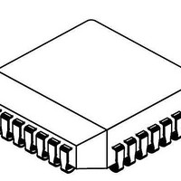
NJM3774FM2 NJR, NJM3774FM2 Datasheet - Page 3

NJM3774FM2
Manufacturer Part Number
NJM3774FM2
Description
IC STEPPER MOTOR DVR DUAL 28PLCC
Manufacturer
NJR
Type
Stepper Motor Controller/Driverr
Datasheet
1.NJM3774FM2.pdf
(9 pages)
Specifications of NJM3774FM2
Applications
Stepper Motor Driver, 2 Phase
Number Of Outputs
1
Current - Output
1A
Voltage - Load
10 V ~ 40 V
Voltage - Supply
4.75 V ~ 5.25 V
Operating Temperature
-20°C ~ 125°C
Mounting Type
Surface Mount
Package / Case
28-PLCC
Product
Stepper Motor Controllers / Drivers
Operating Supply Voltage
7 V
Supply Current
75 mA
Mounting Style
SMD/SMT
Lead Free Status / RoHS Status
Contains lead / RoHS non-compliant
Available stocks
Company
Part Number
Manufacturer
Quantity
Price
Company:
Part Number:
NJM3774FM2
Manufacturer:
JRC
Quantity:
34
Company:
Part Number:
NJM3774FM2
Manufacturer:
JRC
Quantity:
18
Part Number:
NJM3774FM2
Manufacturer:
JRC
Quantity:
20 000
Each channel of the NJM3774 consists of the following sections: an output H-bridge with four transistors, capable
of driving up to 1000mA continuous current to the motor winding; a logic section that controls the output transistors;
an S-R flip-flop; and a comparator. The clock-oscillator is common to both channels.
peak current through the winding via a resistor, R
turn-on period. As the current increases, a voltage develops across the resistor, and is fed back to the comparator.
At the predetermined level defined by the voltage at the reference input V
turning off the output transistors. The current decreases until the clock oscillator triggers the flip-flop, turning on the
output transistors, and the cycle is repeated.
diodes are connected to the circuit externally.
Constant current control is achieved by switching the output current to the windings. This is done by sensing the
The current paths during turn-on, turn-off and phase shift are shown in figure 3. Note that the upper recirculation
FUNCTIONAL DESCRIPTION
Figure 3. Output stage with current paths
during turn-on, turn-off and phase shift.
Motor Current
3
External recirculation diodes
Fast Current Decay
Slow Current Decay
1
1
S
, effectively connected in series with the motor winding during the
V
R
2
MM
S
2
3
R
, the comparator resets the flip-flop,
Time
NJM3774


