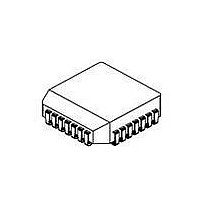
NJM3773FM2 NJR, NJM3773FM2 Datasheet - Page 5

NJM3773FM2
Manufacturer Part Number
NJM3773FM2
Description
IC STEPPER MOTOR DVR DUAL 28PLCC
Manufacturer
NJR
Type
Stepper Motor Controller/Driverr
Datasheet
1.NJM3773D2.pdf
(9 pages)
Specifications of NJM3773FM2
Applications
Stepper Motor Driver, 2 Phase
Number Of Outputs
1
Current - Output
750mA
Voltage - Load
10 V ~ 40 V
Voltage - Supply
4.75 V ~ 5.25 V
Operating Temperature
-20°C ~ 125°C
Mounting Type
Surface Mount
Package / Case
28-PLCC
Product
Stepper Motor Controllers / Drivers
Operating Supply Voltage
7 V
Supply Current
70 mA
Mounting Style
SMD/SMT
Lead Free Status / RoHS Status
Contains lead / RoHS non-compliant
Available stocks
Company
Part Number
Manufacturer
Quantity
Price
Company:
Part Number:
NJM3773FM2
Manufacturer:
NJR
Quantity:
964
Company:
Part Number:
NJM3773FM2
Manufacturer:
JR
Quantity:
12 388
Part Number:
NJM3773FM2
Manufacturer:
JRC
Quantity:
20 000
Notes
1. All voltages are with respect to ground. Currents are positive into, negative out of specified terminal.
2. All ground pins soldered onto a 20 cm
3. Not covered by final test program.
4. Switching duty cycle D = 30%, f
Electrical characteristics over recommended operating conditions, unless otherwise noted. -20 C
Parameter
General
Supply current
Supply current
Total power dissipation
Total power dissipation
Thermal shutdown junction temperature
Turn-off delay
Logic Inputs
Logic HIGH input voltage
Logic LOW input voltage
Logic HIGH input current
Logic LOW input current
Analog Inputs
Input current
Threshold voltage
| V
Motor Outputs
Lower transistor saturation voltage
Lower transistor leakage current
Lower diode forward voltage drop
Upper transistor saturation voltage
Upper transistor leakage current
Upper diode forward voltage drop
Chopper Oscillator
Chopping frequency
Digital filter blanking time
Parameter
Thermal resistance
C1
ELECTRICAL CHARACTERISTICS
THERMAL CHARACTERISTICS
- V
C2
| mismatch
s
= 23.0 kHz.
2
Symbol
Rth
Rth
Rth
Rth
Rth
Rth
Symbol Conditions
I
I
P
P
t
V
V
I
I
I
V
V
f
t
PCB copper area with free air convection, T
CC
CC
d
IH
IL
A
s
b
D
D
IH
IL
C
C,diff
J-GND
J-A
J-GND
J-A
J-GND
J-A
I
I
I
I
V
Dis
V
Notes 2, 3, 4.
V
Notes 2, 3, 4.
T
I
V
V
V
R
V
V
C
C
M
M
M
M
M
A
Conditions
R
MM
MM
I
I
R
MM
MM
DIP package.
DIP package. Note 2.
PLCC package.
PLCC package. Note 2.
EMP package
EMP package
B
T
T
= 100 mA. Note 3. (one channel on).
= 500 mA
= 500 mA
= 500 mA.
= 500 mA.
=500mV. Note 4.
= 2.4 V
= 0.4 V
= 500mV
= 1 kohm. Note 3.
= +25 C, dV
= 4 700 pF, R
= 4 700 pF. Note 3.
1
= 24 V, I
= 24 V, I
=41 V,T
=41 V,T
= Dis
2
= HIGH.
A
A
M1
M1
= +25 C. Dis
= +25 C. Dis
= I
= 700 mA, I
C
/dt
M2
T
= 12 kohm
= 500 mA.
50 mV/ s,
1
1
M2
= Dis
= Dis
= 0 mA.
2
2
= HIGH.
= HIGH.
A
= +25 C.
.
Min
-
-
-
-
-
-
Min
-
-
-
-
-
-
2.0
-
-
-0.2
-0.5
-
-
-
-
-
-
-
-
21.5
-
Typ
11
40
9
35
13
42
Typ
55
7
2.0
1.7
160
1.1
-
-
-
-0.1
-0.2
500
1
0.4
-
1.1
1.1
-
1.1
23.0
1.0
NJM3773
T
Max
70
10
2.3
2.0
-
2.0
-
0.6
20
-
-
-
-
0.8
100
1.3
1.4
100
1.4
24.5
-
Max
-
-
-
-
-
-
j
+125 C.
Unit
mA
mA
W
W
V
V
mA
mV
mV
V
V
V
V
kHz
C
s
A
A
A
A
s
Unit
C/W
C/W
C/W
C/W
C/W
C/W


