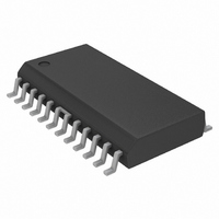
NJM37717E2 NJR, NJM37717E2 Datasheet

NJM37717E2
Specifications of NJM37717E2
Related parts for NJM37717E2
NJM37717E2 Summary of contents
Page 1
GENERAL DESCRIPTION NJM37717 is a stepper motor diver, which consists of a LS-TTL compatible logic input stage, a current sensor, a monostable multivibrator and a high power H-bridge output stage with built-in protection diodes. NJM37717 is a high voltage version ...
Page 2
PIN CONFIGURATIONS PIN DESCRIPTION DIP 1 2 3,14 4,5 12, Figure 2. Pin configurations Symbol Description M Motor output B, Motor current flows from Clock oscillator. Timing pin connect ...
Page 3
Figure 3. Definition of terms FUNCTIONAL DESCRIPTION The NJM37717 is intended to drive a bipolar constant current through one motor winding of a 2-phase stepper motor. Current control is achieved through switched-mode regulation, see figure 4 and 5. Three different ...
Page 4
Current sensor The current sensor contains a reference voltage divider and three comparators for measuring each of the select- able current levels. The motor current is sensed as a voltage drop across the current sensing resistor, R compared with one ...
Page 5
Figure 4. Motor current ( Vertical : 200 mA/div, Horizontal: 1 ms/div, expanded part 100 µs/div Figure 6. Principal operating sequence NJM37717 Figure 5. Output stage with current paths for fast and slow current decay ...
Page 6
ABSOLUTE MAXIMUM RATINGS (Ta=25 Parameter Voltage Logic supply Motor supply Logic inputs Comparator input Reference input Current Motor output current Logic inputs Analog inputs Temperature Operating junction temperature Storage temperature RECOMMENDED OPERATING CONDITIONS (Ta=25 Parameter Logic supply voltage Motor supply ...
Page 7
ELECTRICAL CHARACTERISTICS Electrical characteristics over recommended operating conditions, unless otherwise specified .Ta=25°C,C Parameter General Supply current Total power dissipation Turn-off delay Thermal shutdown junction temperature Logic Inputs Logic HIGH input voltage Logic LOW input voltage Logic HIGH input current Logic ...
Page 8
Applications Information Motor selection Some stepper motors are not designed for continuous operation at maximum current. As the circuit drives a con- stant current through the motor, its temperature can increase, both at low- and high-speed operation. Some stepper motors ...
Page 9
Analog control As the current levels can be continuously controlled by modulating the V achieved. Switching frequency The motor inductance, together with the pulse time, t The choice of motor may then require other values on the R to obtain ...
Page 10
TYPICAL CHARACTERISTICS Figure 11. Typical source saturation vs. output current Figure 14. Typical upper diode voltage drop vs. recirculating current Figure 12. Typical sink saturation vs. output current Figure 15. Typical power dissipation vs. motor current NJM37717 Figure 13. Typical ...


