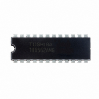
TB6562ANG Toshiba, TB6562ANG Datasheet - Page 13

TB6562ANG
Manufacturer Part Number
TB6562ANG
Description
IC DRIVER DUAL FULL BRDG 24SDIP
Manufacturer
Toshiba
Type
Full Bridge Motor Driverr
Datasheet
1.TB6562AFGOEL.pdf
(19 pages)
Specifications of TB6562ANG
Applications
Stepper Motor Driver, 2 Phase
Number Of Outputs
1
Current - Output
1.5A
Voltage - Supply
10 V ~ 34 V
Operating Temperature
-20°C ~ 85°C
Mounting Type
Through Hole
Package / Case
24-SDIP (0.300", 7.62mm)
Product
Stepper Motor Controllers / Drivers
Operating Supply Voltage
10 V to 34 V
Supply Current
12 mA
Mounting Style
Through Hole
Function
Driver
Vopmax (vm*)
34V (40V)
Io (lpeak)
(1.5A)
Excitation
1/4 step
I/f
phase input (2-bit/phase)
Mixed Decay Mode
no
Package
NDIP24
Rohs Compatible†
yes
Lead Free Status / RoHS Status
Lead free / RoHS Compliant
Voltage - Load
-
Lead Free Status / Rohs Status
Lead free / RoHS Compliant
Other names
TB6562ANG(O)
Reference Voltage Generator
The current value at 100% is determined by applying voltage at the Vref pin.
The value can be calculated as follows:
Thermal Shutdown Circuit (TSD)
The IC incorporates a thermal shutdown circuit. When the junction temperature (T
transistors are turned off.
Overcurrent Protection Circuit (ISD)
The IC incorporates an overcurrent protection circuit to detect voltage flowing through the output transistors. The
overcurrent threshold is 2.5 A (typ.).
one of the transistors, all transistors are turned off.
turned on automatically. If an overcurrent occurs again, the same operation is repeated. To prevent false detection due to
glitches, the circuit turns off the transistors only when current exceeding the overcurrent threshold flows for 10 μs or
longer.
from approximately 1.5 A to 3.5 A.
abnormal conditions and are not guaranteed to prevent damage to the IC.
output short circuits may result in the IC being damaged.
configured so that any overcurrent condition will be eliminated as soon as possible.
After 50 μs (typ.), the output transistors are turned on automatically.
The IC has 40°C temperature hysteresis.
Currents flowing through the eight output transistors are monitored individually. If overcurrent is detected in at least
The IC incorporates a timer to count the 50 μs (typ.) for which the transistors are off. After the 50 μs, the transistors are
The target specification for the overcurrent limiter value (overcurrent threshold) is 2.5 A (typ.), and varies in a range
These protection functions are intended only as a temporary means of preventing output short circuits or other
If the guaranteed operating ranges of this product are exceeded, these protection features may not operate and some
The overcurrent protection feature is intended to protect the IC from temporary short circuits only.
Short circuits persisting over long periods may cause excessive stress and damage the IC. Systems should be
TSD = 160°C (target spec)
ΔTSD = 40°C (target spec)
OUT1
Output current
RS
I O
M
I
LIM
0
I O
Not detected
OUT2
V
I
O
10 μs
CC
(typ.)
(100%) = Vref × 1/10 × 1/RS[A] (X1 = X2 = L)
50 μs
(typ.)
Control
circuit
10 μs
(typ.)
13
50 μs
(typ.)
Decoder
1/10
1/15
1/30
j
) reaches 160°C (typ.), the output
Vref
X1
X2
TB6562ANG/AFG
2007-3-22


