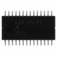
A3979SLPTR-T Allegro Microsystems Inc, A3979SLPTR-T Datasheet

A3979SLPTR-T
Specifications of A3979SLPTR-T
A3979SLPTR-T
Available stocks
Related parts for A3979SLPTR-T
A3979SLPTR-T Summary of contents
Page 1
Microstepping DMOS Driver with Translator Features and Benefits ▪ ±2 output rating ▪ Low R outputs: 0.28 Ω source, 0.22 Ω sink, typical DS(On) ▪ Automatic current decay mode detection/selection ▪ 3.0 to 5.5 V logic supply ...
Page 2
... A3979 Selection Guide Part Number Packing A3979SLPTR-T 4000 pieces per reel Absolute Maximum Ratings Load Supply Voltage Output Current Logic Supply Voltage Logic Input Voltage Range Sense Voltage V Reference Voltage Operating Ambient Temperature Junction Temperature T Storage Temperature DMOS Microstepping Driver with Translator ...
Page 3
A3979 Logic Supply VDD UVLO and Fault Reference Supply REF RC1 4 STEP R C DIR T1 T1 RESET Translator MS1 MS2 HOME 4 SLEEP SR ENABLE V PFD PFD 0.1 µF RC2 AGND (Required) DMOS ...
Page 4
A3979 ELECTRICAL CHARACTERISTICS Characteristics Output Drivers Load Supply Voltage Range Output Leakage Current 2 Output On Resistance Body Diode Forward Voltage Motor Supply Current Control Logic Logic Supply Voltage Range Logic Supply Current Logic Input Voltage Logic Input Current 2 ...
Page 5
A3979 ELECTRICAL CHARACTERISTICS, continued Characteristics Thermal Shutdown Temperature Thermal Shutdown Hysteresis UVLO Enable Threshold UVLO Hysteresis 1 Typical data are for initial design estimations only, and assume optimum manufacturing and application conditions. Performance may vary for individual units, within the ...
Page 6
A3979 (T = +25° STEP MS1/MS2/ DIR/RESET E SLEEP A. Minimum Command Active Time Before Step Pulse (Data Set-Up Time) ..... 200 ns B. Minimum Command Active Time After Step Pulse (Data Hold Time) ............ 200 ns C. ...
Page 7
A3979 The A3979 is a complete micro- Device Operation. stepping motor driver with a built-in translator for easy operation with minimal control lines designed to operate bipolar stepper motors in full-, half-, quarter-, and sixteenth-step modes. The currents ...
Page 8
A3979 The internal PWM current-control cir- Fixed Off-Time. cuitry uses a one-shot timer to control the duration of time that the MOSFETs remain off. The one shot off-time determined by the selection of external resistors, R capacitors, C ...
Page 9
A3979 Synchronous Rectification. cycle is triggered by an internal fixed–off-time cycle, load current recirculates according to the decay mode selected by the control logic. The A3979 synchronous rectification feature turns on the appropriate MOSFETs during the decay of the current, ...
Page 10
A3979 STEP Input HOME Output 100.00 70.71 Phase 1 I OUT1A 0.00 Direction = H (%) –70.71 –100.00 100.00 70.71 Phase 2 I OUT2A 0.00 Direction = H (%) –70.71 –100.00 Figure 2. Decay Mode for Full-Step Increments STEP Input ...
Page 11
A3979 STEP Input HOME Output 100.00 95.69 88.19 83.15 77.30 70.71 63.44 55.56 47.14 38.27 29.03 19.51 Phase 1 9.8 I OUT1A 0.00 Direction = H –9.8 (%) –19.51 –29.03 –38.27 –47.14 –55.56 –63.44 –70.71 –77.30 –83.15 –88.19 –95.69 –100.00 ...
Page 12
A3979 Table 2. Step Sequencing Settings Home microstep position at Step Angle 45º; DIR = H; 360° full steps Phase 1 Full Half 1/4 1/16 Current Step Step Step Step [% I tripMax ] # # # # ...
Page 13
A3979 Terminal List Table Number DMOS Microstepping Driver with Translator Name Description ...
Page 14
A3979 9.70 ±0. 5.00 28X 0.10 C +0.05 0.25 0.65 –0.06 Copyright ©2005-2008, Allegro MicroSystems, Inc. The products described here are manufactured under one or more U.S. patents or U.S. patents pending. Allegro MicroSystems, Inc. ...


