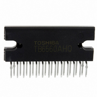
TB6560AHQ(O) Toshiba, TB6560AHQ(O) Datasheet - Page 10

TB6560AHQ(O)
Manufacturer Part Number
TB6560AHQ(O)
Description
IC STEPPER MOTOR DRVR 2PH 25HZIP
Manufacturer
Toshiba
Type
Stepper Motor Driverr
Specifications of TB6560AHQ(O)
Applications
Stepper Motor Driver, 2 Phase
Number Of Outputs
1
Current - Output
3A
Voltage - Load
4.5 V ~ 34 V
Voltage - Supply
4.5 V ~ 5.5 V
Operating Temperature
-30°C ~ 85°C
Mounting Type
Through Hole
Package / Case
25-HZIP
Product
Stepper Motor Controllers / Drivers
Operating Supply Voltage
5 V
Mounting Style
SMD/SMT
Lead Free Status / RoHS Status
Lead free / RoHS Compliant
Other names
TB6560AHQO
TB6560HQ
TB6560HQ(O)
TB6560HQ
TB6560HQO
TB6560HQ
TB6560HQ(O)
TB6560HQ
TB6560HQO
Available stocks
Company
Part Number
Manufacturer
Quantity
Price
Company:
Part Number:
TB6560AHQ(O)
Manufacturer:
Toshiba
Quantity:
1 127
Company:
Part Number:
TB6560AHQ(O)
Manufacturer:
PJ
Quantity:
24
5. Torque Settings (Current Value)
6. Calculation of the Predefined Output Current
7. Protect and M
Rest voltage of output terminal Mo and output terminal Protect reach 0.5 V (max) when I
8. Adjusting the External Capacitor Value (C
Note 1: When the frequency of an input clock signal is high, the C
Note 2: Not tested in production.
Capacitor
Pin State
1000 pF
The ratio of the current necessary for actual operations to the predefined current adjusted by an external
resistor can be selected as follows. The Weak Excitation mode should be selected to set a torque extremely
low like when the motor is at a fixed position.
Since the TQ2 and TQ1 pins have pull-down resistors, the 100% torque setting is selected when TQ2 and
TQ1 are undriven.
To perform a constant current drive, the reference current should be adjusted by an external resistor.
Charging stops when the N
current does not exceed the predefined level.
I
These are open-drain outputs. An external pull-up resistor should be added to these pins when in use.
If the TSD circuit is activated, Protect is driven Low. When the IC enters the Initial state, M
Low.
(t
A triangular-wave is generated internally by CR oscillation. The capacitor is externally connected to the
OSC pin. The recommended capacitor value is between 100 pF and 1000 pF.
Approximate equation: f
(Since this is an approximation formula, the calculation result may not be exactly equal to the actual
value.)
The approximate values are shown below.
The minimum clock pulse width (t
330 pF
100 pF
High-Z
OUT
TQ2
Low
W(CLK)
H
H
L
L
Example: To set the peak current to 1 A, the value of an external resistor should be 0.5 Ω.
of an input clock pulse does not become extremely high (should be around 50% or lower).
(A) = 0.5 (V) / R
)
Oscillating Frequency
Thermal shutdown
O
Normal operation
TQ1
H
H
L
L
Output Pins
NF
130 kHz
400 kHz
Protect
44 kHz
OSC
(Ω)
FA
= 1/{ C
(N
FB
W(CLK)
(Weak excitation)
OSC
) voltage reaches 0.5 V (when the torque setting is 100%) so that a
Current Ratio
× 1.5 × (10/ C
100%
Minimum Clock Pulse Width t
75%
50%
20%
Other than the initial state
) corresponds to the external capacitor (C
Initial state
10
M
OSC
OSC
O
90 μ s (Note 2)
10 μ s (Note 2)
+ 1)/66} × 1000 kHz
) and Minimum Clock Pulse Width
30 μ s
OSC
value should be small so that the duty cycle
W(CLK)
Open-drain connection
(Note 1)
TB6560AHQ/AFG
OSC
O
is 1 mA.
) as follows:
O
2009-07-10
is driven


