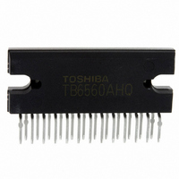
TB6560AHQ(O) Toshiba, TB6560AHQ(O) Datasheet - Page 29

TB6560AHQ(O)
Manufacturer Part Number
TB6560AHQ(O)
Description
IC STEPPER MOTOR DRVR 2PH 25HZIP
Manufacturer
Toshiba
Type
Stepper Motor Driverr
Specifications of TB6560AHQ(O)
Applications
Stepper Motor Driver, 2 Phase
Number Of Outputs
1
Current - Output
3A
Voltage - Load
4.5 V ~ 34 V
Voltage - Supply
4.5 V ~ 5.5 V
Operating Temperature
-30°C ~ 85°C
Mounting Type
Through Hole
Package / Case
25-HZIP
Product
Stepper Motor Controllers / Drivers
Operating Supply Voltage
5 V
Mounting Style
SMD/SMT
Lead Free Status / RoHS Status
Lead free / RoHS Compliant
Other names
TB6560AHQO
TB6560HQ
TB6560HQ(O)
TB6560HQ
TB6560HQO
TB6560HQ
TB6560HQ(O)
TB6560HQ
TB6560HQO
Available stocks
Company
Part Number
Manufacturer
Quantity
Price
Company:
Part Number:
TB6560AHQ(O)
Manufacturer:
Toshiba
Quantity:
1 127
Company:
Part Number:
TB6560AHQ(O)
Manufacturer:
PJ
Quantity:
24
Application Circuit Example
Usage Considerations
Note: Capacitors for the power supply lines should be connected as close to the IC as possible.
External
MCU
input
or
•
•
•
•
A large current might abruptly flow through the IC in case of a short-circuit across its outputs, a short-circuit
to power supply or a short-circuit to ground, leading to a damage of the IC. Also, the IC or peripheral parts
may be permanently damaged or emit smoke or fire resulting in injury especially if a power supply pin
(V
or any other pins. These possibilities should be fully considered in the design of the output, V
ground lines.
A fuse should be connected to the power supply line. The rated maximum current of the TB6560AHQ is
3.5 A/phase and that of the TB6560AFG is 2.5 A/phase. Considering those maximum ratings, an
appropriate fuse must be selected depending on operating conditions of a motor to be used. Toshiba
recommends that a fast-blow fuse be used.
The power-on sequence described on page 28 must be properly followed.
If a voltage outside the operating range specified on page 6 (4.5 ≤ V
V
damaged. Ensure that the voltage range does not exceed the upper and lower limits of the specified range.
MA/B
DD
5 V
, V
) is applied, the IC may not operate properly or the IC and peripheral parts may be permanently
MA
, V
10 μ F
R1
MB
) or an output pin (OUT_AP, OUT_AM, OUT_BP, OUT_BM) is short-circuited to adjacent
RESET
CLK
ENABLE
M1
M2
CW/CCW
DCY1
DCY2
TQ1
TQ2
Protect
R2
1 μ F
M
O
Current
control
100 pF ∼ − 400 kHz
Logic
V
DD
NFCompA
29
OSC
V
MA
PWM control
PWM control
SGND
H-SW A
H-SW B
circuit
circuit
NFCompB
V
MB
47 μ F
Fuse
DD
PGND
≤ 5.5, 4.5 ≤ V
OUT_AM
OUT_BM
OUT_AP
OUT_BP
1 μ F
N
N
FA
FB
TB6560AHQ/AFG
0.5 Ω : I
24 V
R
R
MA/B
OUT
NFA
NFB
(max) = 1.0 A
≤ 34, V
M
2008-04-07
DD
, V
DD
M
, and
≤


