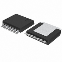
BD6232HFP-TR Rohm Semiconductor, BD6232HFP-TR Datasheet - Page 9

BD6232HFP-TR
Manufacturer Part Number
BD6232HFP-TR
Description
IC H-BRIDGE DVR 36V 1CH 2A HRP7
Manufacturer
Rohm Semiconductor
Series
-r
Type
Half Bridge Driverr
Datasheet
1.BD6230HFP-TR.pdf
(17 pages)
Specifications of BD6232HFP-TR
Applications
DC Motor Driver
Number Of Outputs
1
Current - Output
2A
Voltage - Supply
6 V ~ 32 V
Operating Temperature
-40°C ~ 85°C
Mounting Type
Surface Mount
Package / Case
HRP-7
No. Of Outputs
1
Output Current
2A
Output Voltage
36V
Supply Voltage Range
6V To 32V
Driver Case Style
HRP
No. Of Pins
7
Operating Temperature Range
-40°C To +85°C
Svhc
No SVHC
Evaluation Tools
-
Voltage - Load
-
Operating Supply Voltage
6 V to 32 V
Supply Current
2.5 mA
Mounting Style
SMD/SMT
Motor Type
H-Bridge
Rohs Compliant
Yes
Lead Free Status / RoHS Status
Lead free / RoHS Compliant
Voltage - Load
-
Lead Free Status / Rohs Status
Lead free / RoHS Compliant
Available stocks
Company
Part Number
Manufacturer
Quantity
Price
Company:
Part Number:
BD6232HFP-TR
Manufacturer:
TRIDENT
Quantity:
230
Company:
Part Number:
BD6232HFP-TR
Manufacturer:
ROHM Semiconductor
Quantity:
1 880
Functional descriptions
○
BD6230, BD6231, BD6232, BD6235, BD6236, BD6237
c
www.rohm.com
2009 ROHM Co., Ltd. All rights reserved.
1) Operation modes
a) Stand-by mode
b) Forward mode
c) Reverse mode
d) Brake mode
Stand-by operates independently of the VREF pin voltage. In stand-by mode, all internal circuits are turned off,
including the output power transistors. Motor output goes to high impedance. If the motor is running at the switch to
stand-by mode, the system enters an idling state because of the body diodes. However, when the system switches
to stand-by from any other mode (except the brake mode), the control logic remains in the high state for at least
50µs before shutting down all circuits.
This operating mode is defined as the forward rotation of the motor when the OUT1 pin is high and OUT2 pin is low.
When the motor is connected between the OUT1 and OUT2 pins, the current flows from OUT1 to OUT2. For
operation in this mode, connect the VREF pin with VCC pin.
This operating mode is defined as the reverse rotation of the motor when the OUT1 pin is low and OUT2 pin is high.
When the motor is connected between the OUT1 and OUT2 pins, the current flows from OUT2 to OUT1. For
operation in this mode, connect the VREF pin with VCC pin.
This operating mode is used to quickly stop the motor (short circuit brake). It differs from the stand-by mode
because the internal control circuit is operating in the brake mode. Please switch to the stand-by mode (rather than
the brake mode) to save power and reduce consumption.
* Hi-Z is the off state of all output transistors. Please note that this is the state of the connected diodes, which differs from that of the mechanical relay.
X : Don’t care
a
b
c
d
e
g
h
OFF
OFF
f
i
j
a) Stand-by mode
PWM
PWM
FIN
H
H
H
H
L
L
L
L
M
PWM
PWM
RIN
H
H
H
H
L
L
L
L
OFF
OFF
OFF
Fig.37 Four basic operations (output stage)
Option
Option
ON
VREF
VCC
VCC
VCC
VCC
VCC
VCC
b) Forward mode
X
X
__________
__________
__________
OUT1
M
PWM
PWM
PWM
Hi-Z*
H
H
H
L
L
L
Table 7 Logic table
9/16
OFF
ON
__________
__________
__________
OUT2
PWM
PWM
PWM
Hi-Z*
H
H
H
L
L
L
OFF
ON
c) Reverse mode
Stand-by (idling)
Forward (OUT1 > OUT2)
Reverse (OUT1 < OUT2)
Brake (stop)
Forward (PWM control mode A)
Reverse (PWM control mode A)
Forward (PWM control mode B)
Reverse (PWM control mode B)
Forward (VREF control)
Reverse (VREF control)
M
ON
OFF
Operation
OFF
ON
d) Brake mode
2009.08 - Rev.C
M
Technical Note
OFF
ON


