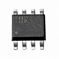
IPS521G International Rectifier, IPS521G Datasheet - Page 5

IPS521G
Manufacturer Part Number
IPS521G
Description
IC MOSFET HS PWR SW 5A 8-SOIC
Manufacturer
International Rectifier
Type
High Sider
Datasheet
1.IPS521G.pdf
(9 pages)
Specifications of IPS521G
Input Type
Non-Inverting
Number Of Outputs
1
On-state Resistance
80 mOhm
Current - Output / Channel
1.6A
Current - Peak Output
10A
Voltage - Supply
5.5 V ~ 35 V
Operating Temperature
-40°C ~ 150°C
Mounting Type
Surface Mount
Package / Case
8-SOIC (3.9mm Width)
Current, Leakage, Offset
50 mA
Current, Supply
1.6 A
Package Type
SOIC-8
Polarization
N-Channel
Power Dissipation
1 W
Resistance, Drain To Source On
100 Milliohms
Temperature, Operating, Maximum
+150 °C
Temperature, Operating, Minimum
–40 °C
Thermal Resistance, Junction To Ambient
125 °C/W
Time, Turn-off Delay
35 ms
Time, Turn-on Delay
10 ms
Voltage, Input
7 V
Voltage, Input, High Level
5.5 V
Voltage, Input, Low Level
0.9 V
Voltage, Supply
65 V
Lead Free Status / RoHS Status
Contains lead / RoHS non-compliant
Other names
*IPS521G
Available stocks
Company
Part Number
Manufacturer
Quantity
Price
Part Number:
IPS521G
Manufacturer:
IR
Quantity:
20 000
Company:
Part Number:
IPS521GTR
Manufacturer:
AMIS
Quantity:
34
Part Number:
IPS521GTRBPF
Manufacturer:
IR
Quantity:
20 000
Company:
Part Number:
IPS521GTRPBF
Manufacturer:
IR
Quantity:
13 000
www.irf.com
Vin
Vout
Vcc - 5V
Figure 3 - Switching times definition (turn-on)
Iout
Out
90%
( see Appl . Notes to evaluate power dissipation )
Vin
Ids
Vcc
10%
Td on
Turn on energy with a resistive or an
Figure 1 - Active clamp waveforms
Iout1
inductive load
0 V
dV/dt on
Tr 1
Resistive load
( + Vcc )
V clamp
Eon1
Eon2
Tr 2
Inductive load
Iout2
T clamp
E1(t)
E2 (t)
Vin
Tsd-
Tsd+
Vout
(160 ° )
90%
Vin
Iout
10%
T
Ilim.
Td off
Figure 4 - Switching times definition (turn-off)
5 V
0 V
limiting
Figure 2 - Protection timing diagram
Tf
dV/dt off
T shutdown
IPS521G
cycling
5


