ISL6700IR Intersil, ISL6700IR Datasheet - Page 5
ISL6700IR
Manufacturer Part Number
ISL6700IR
Description
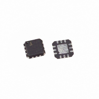
IC DRIVER HALF BRIDGE DUAL 12QFN
Manufacturer
Intersil
Datasheet
1.ISL6700IBZ.pdf
(8 pages)
Specifications of ISL6700IR
Configuration
Half Bridge
Input Type
PWM
Delay Time
70ns
Current - Peak
1.4A
Number Of Configurations
1
Number Of Outputs
2
High Side Voltage - Max (bootstrap)
80V
Voltage - Supply
9 V ~ 15 V
Operating Temperature
-40°C ~ 125°C
Mounting Type
Surface Mount
Package / Case
12-QFN
Lead Free Status / RoHS Status
Contains lead / RoHS non-compliant
Available stocks
Company
Part Number
Manufacturer
Quantity
Price


Electrical Specifications
Switching Specifications
Pin Descriptions
GATE DRIVER OUTPUT PINS: LO & HO
Low Level Output Voltage
High Level Output Voltage
Peak Pullup Current
Peak Pulldown Current
Lower Turn-off Propagation Delay
(LI Falling to LO Falling)
Upper Turn-off Propagation Delay
(HI Falling to HO Falling)
Lower Turn-on Propagation Delay
(LI Rising to LO Rising)
Upper Turn-on Propagation Delay
(HI Rising to HO Rising)
Deadtime, (t
Deadtime, (t
Rise Time
Fall Time
Delay Matching: Lower Turn-On and Upper Turn-Off
Delay Matching: Lower Turn-Off and Upper Turn-On
SYMBOL
EPAD
V
V
HO
LO
HS
HB
HI
LI
DD
SS
PARAMETERS
HPLH
LPLH
Positive supply to control logic and lower gate drivers. De-couple this pin to V
Logic level input that controls the HO output.
Logic level input that controls the LO output.
Chip negative supply, generally will be ground.
Low-side output. Connect to gate of low-side power MOSFET.
High-side source connection. Connect to source of high-side power MOSFET. Connect negative side of bootstrap capacitor to this
pin.
High-side output. Connect to gate of high-side power MOSFET.
High-side bootstrap supply. External bootstrap diode and capacitor are required. Connect cathode of bootstrap diode and positive
side of bootstrap capacitor to this pin.
Exposed pad. Connect to ground or float. The EPAD is electrically isolated from all other pins.
- t
- t
PARAMETERS
HPHL
LPHL
)
)
5
V
V
DD
DD
= V
= V
SYMBOL
V
HB
DD
HB
V
I
I
O
O
= 12V, V
OL
-V
= 12V, V
+
-
OH
SS
I
I
V
V
OUT
OUT
SS
SYMBOL
OUT
OUT
DHt
DLt
t
t
t
t
t
t
MOFF
HPHL
HPLH
= V
LPHL
LPLH
MON
= V
t
t
R
F
= 0A
= 0A
ON
ON
= 0V
= 12V
HS
HS
TEST CONDITIONS
= 0V, No Load on LO or HO, Unless Otherwise Specified (Continued)
ISL6700
= 0V, No Load on LO or HO, Unless Otherwise Specified
LI, HI switched simultaneously
DESCRIPTION
CONDITIONS
TEST
SS
. Connect anode of bootstrap diode to this pin.
MIN
-
-
-
-
MIN
0
0
-
-
-
-
-
-
-
-
T
J
T
TYP
= 25°C
J
1.4
1.3
TYP
-
-
= 25°C
-15
45
60
75
70
24
17
5
5
8
MAX
0.1
0.1
MAX
-
-
50
75
82
75
20
20
20
25
-
-
T
MIN
J
MIN
T
TO 125°C
-
-
-
-
= -40°C TO
0
0
J
-
-
-
-
-
-
-
-
125°C
= -40°C
MAX
December 29, 2004
MAX
0.1
0.1
65
90
95
95
25
25
25
30
-
-
-
-
UNITS
UNITS
FN9077.6
ns
ns
ns
ns
ns
ns
ns
ns
ns
ns
V
V
A
A
Related parts for ISL6700IR
Image
Part Number
Description
Manufacturer
Datasheet
Request
R

Part Number:
Description:
Intersil Corporation [CMOS Serial Controller Interface]
Manufacturer:
Intersil Corporation
Datasheet:
Part Number:
Description:
Manufacturer:
Intersil Corporation
Datasheet:
Part Number:
Description:
357-036-542-201 CARDEDGE 36POS DL .156 BLK LOPRO
Manufacturer:
Intersil Corporation
Datasheet:
Part Number:
Description:
1024-Word x 4-Bit LSI Static RAM
Manufacturer:
Intersil Corporation
Datasheet:
Part Number:
Description:
General Purpose NPN Transistor Arrays FN341.4
Manufacturer:
Intersil Corporation
Datasheet:
Part Number:
Description:
CMOS 16-Bit Microprocessor
Manufacturer:
Intersil Corporation
Datasheet:
Part Number:
Description:
Manufacturer:
Intersil Corporation
Datasheet:
Part Number:
Description:
Manufacturer:
Intersil Corporation
Datasheet:
Part Number:
Description:
Manufacturer:
Intersil Corporation
Datasheet:
Part Number:
Description:
Manufacturer:
Intersil Corporation
Datasheet:
Part Number:
Description:
CMOS 6-Bit Latch and Decoder Memory Interfaces
Manufacturer:
Intersil Corporation
Datasheet:
Part Number:
Description:
CA3046General Purpose NPN Transistor Arrays
Manufacturer:
Intersil Corporation
Datasheet:
Part Number:
Description:
Manufacturer:
Intersil Corporation
Datasheet:
Part Number:
Description:
TR909 DLC/FLC SLIC with Low Power Standby
Manufacturer:
Intersil Corporation
Datasheet:
Part Number:
Description:
Manufacturer:
Intersil Corporation
Datasheet: