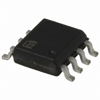
MIC5021BM Micrel Inc, MIC5021BM Datasheet - Page 9

MIC5021BM
Manufacturer Part Number
MIC5021BM
Description
IC DRIVER MOSFET HISIDE HS 8SOIC
Manufacturer
Micrel Inc
Datasheet
1.MIC5021YM_TR.pdf
(10 pages)
Specifications of MIC5021BM
Configuration
High-Side
Input Type
Non-Inverting
Delay Time
500ns
Number Of Configurations
1
Number Of Outputs
1
Voltage - Supply
12 V ~ 36 V
Operating Temperature
-40°C ~ 85°C
Mounting Type
Surface Mount
Package / Case
8-SOIC (3.9mm Width)
Number Of Drivers
1
Driver Configuration
Non-Inverting
Driver Type
High Side
Input Logic Level
TTL
Rise Time
500ns
Fall Time
500ns
Frequency (max)
150MHz
Operating Supply Voltage (max)
36V
Operating Supply Voltage (min)
12V
Operating Supply Voltage (typ)
15V
Turn Off Delay Time
1.5ps
Turn On Delay Time (max)
1ns
Operating Temp Range
-40C to 85C
Operating Temperature Classification
Industrial
Mounting
Surface Mount
Pin Count
8
Package Type
SOIC
Lead Free Status / RoHS Status
Contains lead / RoHS non-compliant
Current - Peak
-
High Side Voltage - Max (bootstrap)
-
Lead Free Status / RoHS Status
Not Compliant, Contains lead / RoHS non-compliant
Available stocks
Company
Part Number
Manufacturer
Quantity
Price
Company:
Part Number:
MIC5021BM
Manufacturer:
MICREL
Quantity:
115
Remote Overcurrent Limiting Reset
In circuit breaker applications where the MIC5021 maintains
an off condition after an overcurrent condition is sensed, the
C
Switching Q1 on pulls C
output off when an overcurrent is sensed. Switching Q1 off
causes C
20µs and continues to retry until the overcurrent condition
is removed.
For demonstration purposes, a 680Ω load resistor and 3Ω
sense resistor will produce an overcurrent condition when the
load’s supply (V+) is approximately 12V or greater.
Low-Temperature Operation
As the temperature of the MIC5021AJB (extended temperature
range version—no longer available) approaches –55°C, the
driver’s off-state, gate-output offset from ground increases.
If the operating environment of the MIC5021AJB includes
low temperatures (–40°C to –55°C), add an external 2.2MΩ
resistor as shown in Figures 12a or 12b. This assures that
the driver’s gate-to-source voltage is far below the external
MOSFET’s gate threshold voltage, forcing the MOSFET
fully off.
July 2005
MIC5021
T
pin can be used to reset the MIC5021.
Maintained (L)
Retry (H)
TTL Input
(example)
T
74HC04
Figure 11. Remote Control Circuit
to appear open. The MIC5021 retries in about
10k to
100k
10µF
2N3904
Q1
T
low which keeps the MIC5021
1
2
3
4
V
Input
C
Gnd
DD
T
MIC5021
V
Sense-
Sense+
B O O S T
Gate
8
7
6
5
+12V to +20V
0.01
µF
N-Channel
Power
MO S F E T
R
Load
S E N S E
GATE
9
The gate-to-source configuration (refer to Figure 12a) is
appropriate for resistive and inductive loads. This also causes
the smallest decrease in gate output voltage.
The gate-to-ground configuration (refer to Figure 12b) is ap-
propriate for resistive, inductive, or capacitive loads. This
configuration will decrease the gate output voltage slightly
more than the circuit shown in Figure 12a.
TTL Input
TTL Input
Figure 12b. Gate-to-Ground Pull Down
Figure 12a. Gate-to-Source Pull Down
10µF
10µF
1
2
3
4
1
2
3
4
MIC5021AJB
–40 ° C to –55 ° C
V
Input
C
Gnd
add resistor for
MIC5021AJB
DD
–40 ° C to –55 ° C
T
V
Input
C
Gnd
add resistor for
DD
T
operation
Sense-
Sense+
V
operation
B O O S T
V
Sense-
Sense+
Gate
B O O S T
Gate
8
7
6
5
8
7
6
5
2.7
nF
2.2M
+12V to +36V
2.7
nF
2.2M
+12V to +36V
R
Micrel, Inc.
Load
S E N S E
MIC5021
R
Load
S E N S E


