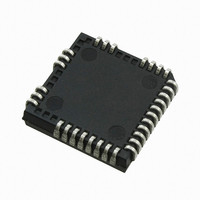
IR2136J International Rectifier, IR2136J Datasheet - Page 5

IR2136J
Manufacturer Part Number
IR2136J
Description
IC DRIVER BRIDGE 3-PHASE 44-PLCC
Manufacturer
International Rectifier
Datasheet
1.IR21362JTRPBF.pdf
(36 pages)
Specifications of IR2136J
Configuration
3 Phase Bridge
Input Type
Inverting
Delay Time
425ns
Current - Peak
200mA
Number Of Configurations
1
Number Of Outputs
3
High Side Voltage - Max (bootstrap)
600V
Voltage - Supply
10 V ~ 20 V
Operating Temperature
-40°C ~ 125°C
Mounting Type
Surface Mount
Package / Case
44-PLCC (32 Leads)
Lead Free Status / RoHS Status
Contains lead / RoHS non-compliant
Other names
*IR2136J
Available stocks
Company
Part Number
Manufacturer
Quantity
Price
Company:
Part Number:
IR2136J
Manufacturer:
International Rectifier
Quantity:
10 000
Company:
Part Number:
IR2136JPBF
Manufacturer:
International Rectifier
Quantity:
10 000
Company:
Part Number:
IR2136JTR
Manufacturer:
International Rectifier
Quantity:
10 000
Company:
Part Number:
IR2136JTRPBF
Manufacturer:
International Rectifier
Quantity:
10 000
Dynamic Electrical Characteristics
V
Note: For high side PWM, HIN pulse width must be ≥ 1 µs.
Note 1: A shoot-through prevention logic prevents LO1,2,3 and HO1,2,3 for each channel from turning on simultaneously.
Note 2: UVCC is not latched, when V
Note 3: When ITRIP < V
www.irf.com
CC
<UVCC
= V
Symbol
VCC
15 V
15 V
15 V
15 V
t
FLTCLR
MDT
BS
t
t
PM
ITRIP
t
FILIN
DT
MT
t
t
t
FLT
t
EN
on
off
t
t
bl
r
f
= V
BIAS
= 15 V, V
<UVBS
VBS
15 V
15 V
15 V
X
ITRIP
Turn-on propagation delay
Turn-off propagation delay
Turn-on rise time
Turn-off fall time
ENABLE low to output shutdown
propagation delay
ITRIP to output shutdown propagation delay
ITRIP blanking time
ITRIP to FAULT propagation delay
Input filter time (HIN, LIN)
(IR213(6,62,63,65,68) only)
FAULT clear time RCIN: R = 2 MΩ, C = 1 nF
Deadtime
Matching delay ON and OFF
Matching delay, max (t
(t
Output pulse width matching (pwin-pwout) (Fig.2)
on
S1,2,3
, t
, FAULT returns to high-impedance after RCIN pin becomes greater than 8 V (@ V
off
are applicable to all 3 channels)
= V
SS
CC
>V
= COM, T
ITRIP
0 V
0 V
0 V
> UV
X
ITRIP
Definition
CC
on
, FAULT returns to high impedance.
A
, t
IR213(6,62,63,65,66,67,68)(J&S) & PbF
= 25 °C and CL = 1000 pF unless otherwise specified.
off
) – min (t
ENABLE
5 V
5 V
5 V
0 V
X
IR2136(2,3,5,8) 300
IR2136(6,7)
IR2136(2,3,5,8) 250
IR2136(6,7)
IR2136(2,3,5,8) 300
IR2136(6,7)
on
, t
off
),
0 (note 1)
0 (note 2)
high imp
high imp
high imp
FAULT
Min Typ Max Units
100
500
100
400
100
220
1.3
—
—
—
—
—
—
—
1.65
425
400
125
450
250
750
150
290
250
180
600
200
50
40
25
40
LIN1,2,3
LIN1,2,3
LO1,2,3
1000
0
0
0
550
550
190
600
400
800
360
75
75
70
75
—
—
—
—
2
ms
ns
ns
V
V
V
V
V
Conditions
V
External dead
time >400 ns
IN
IN
IN
IN
IN
HIN1,2,3
HO1,2,3
V
V
V
IN,
ITRIP
ITRIP
ITRIP
= 0 V or 5 V
= 0 V or 5 V
= 0 V & 5 V
= 0 V & 5 V
= 0 V & 5 V
V
or 5 V
Test
CC
0
0
0
0
EN
= 5 V
= 5 V
= 0 V
= 15 V).
= 0 V
5


