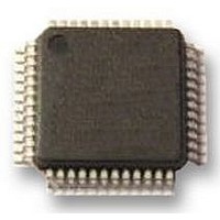
A4935KJP-T Allegro Microsystems Inc, A4935KJP-T Datasheet - Page 4

A4935KJP-T
Manufacturer Part Number
A4935KJP-T
Description
IC MOSFET DRIVER 3PH AUTO 48LQFP
Manufacturer
Allegro Microsystems Inc
Datasheet
1.A4935KJP-T.pdf
(24 pages)
Specifications of A4935KJP-T
Configuration
3 Phase Bridge
Input Type
PWM
Delay Time
90ns
Number Of Configurations
1
Number Of Outputs
3
Voltage - Supply
5.5 V ~ 50 V
Operating Temperature
-40°C ~ 150°C
Mounting Type
Surface Mount
Package / Case
48-LFQFP Exposed Pad
Device Type
Motor
Module Configuration
3-Phase Bridge
Peak Output Current
150mA
Output Resistance
8ohm
Input Delay
90ns
Output Delay
90ns
Supply Voltage Range
3V To 5.5V
Driver Case Style
LQFP
No. Of Pins
48
Operating Temperature Range
-40°C To +150°C
Rohs Compliant
Yes
Lead Free Status / RoHS Status
Lead free / RoHS Compliant
Current - Peak
-
High Side Voltage - Max (bootstrap)
-
Lead Free Status / RoHS Status
Lead free / RoHS Compliant, Lead free / RoHS Compliant
Available stocks
Company
Part Number
Manufacturer
Quantity
Price
Company:
Part Number:
A4935KJP-T
Manufacturer:
Allegro MicroSystems, LLC
Quantity:
10 000
A4935
Continued on the next page…
ELECTRICAL CHARACTERISTICS valid at T
Supply and Reference
Load Supply Voltage Functional
Operating Range
Load Supply Quiescent Current
Logic Supply Voltage
Logic Supply Quiescent Current
VREG Output Voltage
Bootstrap Diode Forward Voltage
Bootstrap Diode Resistance
Bootstrap Diode Current Limit
Top-off Charge Pump Current Limit
High-Side Gate Drive Static Load Resistance
Gate Output Drive
Turn-On Time
Turn-Off Time
Pullup On Resistance
Pulldown On Resistance
GHx Output Voltage
GLx Output Voltage
Turn-Off Propagation Delay
Turn-On Propagation Delay
Propagation Delay Matching, Phase-to-Phase
Propagation Delay Matching, On-to-Off
Characteristics
1
2
2
J
R
R
Symbol
= –40°C to 150°C, V
V
I
I
DS(on)UP
DS(on)DN
DBOOT
TOCPM
R
V
V
V
t
t
∆t
I
I
I
∆t
I
V
V
fBOOT
P(on)
P(off)
BBQ
DDQ
DDS
BBS
REG
GHX
r
GSH
GLX
t
DD
t
BB
D
OO
PP
r
f
Automotive 3-Phase MOSFET Driver
RESET = high, outputs = low, V
RESET = low, Sleep mode, V
RESET = high, outputs = low
RESET = low
V
7.5 V < V
6 V < V
5.5 V < V
I
I
r
C
C
T
T
T
T
Bootstrap capacitor fully charged
Input change to unloaded gate output
change
Input change to unloaded gate output
change
Measured between corresponding
transition points on two sequential phases
Measured across one phase
D
D
D(100mA)
(V
J
J
J
J
BB
LOAD
LOAD
= 10 mA
= 100 mA
fBOOT(150mA)
= 25°C, I
= 150°C, I
= 25°C, I
= 150°C, I
> 9 V, I
= 1 nF, 20% to 80%
= 1 nF, 80% to 20%
BB
=
BB
BB
≤ 7.5 V, I
DD
REG
GHx
GLx
Test Conditions
≤ 9 V, I
≤ 6 V, I
GHx
GLx
= 3 to 5.5 V, V
– V
= 150 mA
= –150 mA
= 0 to 15 mA
= 150 mA
= –150 mA
fBOOT(50mA)
REG
REG
REG
= 0 to 10 mA
= 0 to 9 mA
< 8 mA
BB
) / 100 mA
BB
BB
= 12 V
= 7 to 50 V, unless noted otherwise
= 12 V
115 Northeast Cutoff
1.508.853.5000; www.allegromicro.com
Allegro MicroSystems, Inc.
Worcester, Massachusetts 01615-0036 U.S.A.
2×V
Min.
V
– 2.5
– 0.2
– 0.2
12.5
12.5
250
250
V
5.5
3.0
8.5
0.4
1.5
10
60
60
REG
–
–
–
–
6
–
–
–
6
2
3
–
–
Cx
BB
Typ.
500
400
9.5
0.7
2.2
4.5
10
13
13
10
35
20
13
90
90
10
10
–
–
–
4
–
–
–
8
3
–
–
Max.
13.80
13.80
750
150
150
5.5
1.0
2.8
50
14
10
10
20
12
16
–
6
–
–
–
–
–
–
4
6
–
–
–
Units
mA
mA
mA
kΩ
μA
μA
μA
ns
ns
ns
ns
ns
ns
V
V
V
V
V
V
V
V
Ω
Ω
Ω
Ω
Ω
V
V
4


