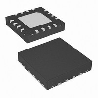
ISL6597CRZ Intersil, ISL6597CRZ Datasheet - Page 9

ISL6597CRZ
Manufacturer Part Number
ISL6597CRZ
Description
IC MOSFET DRVR DUAL SYNC 16-QFN
Manufacturer
Intersil
Datasheet
1.ISL6597CRZ.pdf
(10 pages)
Specifications of ISL6597CRZ
Configuration
High and Low Side, Synchronous
Input Type
Non-Inverting
Delay Time
18ns
Number Of Configurations
2
Number Of Outputs
4
High Side Voltage - Max (bootstrap)
36V
Voltage - Supply
4.5 V ~ 5.5 V
Operating Temperature
0°C ~ 70°C
Mounting Type
Surface Mount
Package / Case
16-VQFN Exposed Pad, 16-HVQFN, 16-SQFN, 16-DHVQFN
Lead Free Status / RoHS Status
Lead free / RoHS Compliant
Current - Peak
-
upper MOSFET to suppress the Miller coupling effect. The
value of the resistor depends mainly on the input voltage’s
rate of rise, the C
threshold of the upper MOSFET. A higher dV/dt, a lower
C
FET will require a smaller resistor to diminish the effect of
the internal capacitive coupling. For most applications, the
integrated 20kΩ typically sufficient, not affecting normal
performance and efficiency.
The coupling effect can be roughly estimated with the
following equations, which assume a fixed linear input ramp
and neglect the clamping effect of the body diode of the
upper drive and the bootstrap capacitor. Other parasitic
components such as lead inductances and PCB
capacitances are also not taken into account. These
equations are provided for guidance purpose only.
Therefore, the actual coupling effect should be examined
using a very high impedance (10MΩ or greater) probe to
ensure a safe design margin.
DS
/C
GS
ratio, and a lower gate-source threshold upper
GD
/C
GS
ratio, as well as the gate-source
9
ISL6597
V
R
GS_MILLER
FIGURE 6. GATE TO SOURCE RESISTOR TO REDUCE
=
VCC
R
UGPH
UPPER MOSFET MILLER COUPLING
=
+
DU
DL
R
dV
------- R C
dt
GI
⋅
⋅
C
PHASE
BOOT
rss
UGATE
rss
C
⎛
⎜
⎜
⎜
⎜
⎝
BOOT
1 e
=
–
C
--------------------------------- -
dV
------ - R C
GD
dt
G
–
⋅
V
DS
R
⋅ iss
C
GI
GD
C
C
⎞
⎟
⎟
⎟
⎟
⎠
iss
GS
S
=
VIN
C
Q
GD
UPPER
D
May 4, 2007
(EQ. 5)
+
FN9165.1
C
C
DS
GS


