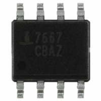
ICL7667CBAZA-T Intersil, ICL7667CBAZA-T Datasheet - Page 2

ICL7667CBAZA-T
Manufacturer Part Number
ICL7667CBAZA-T
Description
IC MOSFET DRIVER DUAL 8-SOIC
Manufacturer
Intersil
Datasheet
1.ICL7667CPAZ.pdf
(10 pages)
Specifications of ICL7667CBAZA-T
Configuration
Low-Side
Input Type
Inverting
Delay Time
20ns
Current - Peak
1A
Number Of Configurations
2
Number Of Outputs
2
Voltage - Supply
4.5 V ~ 15 V
Operating Temperature
0°C ~ 70°C
Mounting Type
Surface Mount
Package / Case
8-SOIC (3.9mm Width)
Rohs Compliant
Yes
Lead Free Status / RoHS Status
Lead free / RoHS Compliant
High Side Voltage - Max (bootstrap)
-
Other names
ICL7667CBAZA-TTR
Available stocks
Company
Part Number
Manufacturer
Quantity
Price
Company:
Part Number:
ICL7667CBAZA-T
Manufacturer:
MICROCHIP
Quantity:
1 001
Electrical Specifications
Absolute Maximum Ratings
Supply Voltage V+ to V- . . . . . . . . . . . . . . . . . . . . . . . . . . . . . . .±18V
Input Voltage . . . . . . . . . . . . . . . . . . . . . . . . . . V- -0.3V to V+ +0.3V
Package Dissipation, T
Operating Conditions
ICL7667C. . . . . . . . . . . . . . . . . . . . . . . . . . . . . . . . . . . . 0° to +70°C
Supply Voltages: V+ = +4.5V to +15V; V- = Ground to -15V
Logic Inputs: Logic Low = V- < Vin < 0.8V ; Logic High = 2.0V< Vin <
V+
CAUTION: Do not operate at or near the maximum ratings listed for extended periods of time. Exposure to such conditions may adversely impact product reliability and
result in failures not covered by warranty.
NOTES:
DC SPECIFICATIONS
Logic 1 Input Voltage
Logic 1 Input Voltage
Logic 0 Input Voltage
Logic 0 Input Voltage
Input Current
Output Voltage High
Output Voltage Low
Output Resistance
Output Resistance
Power Supply Current
Power Supply Current
SWITCHING SPECIFICATIONS
Delay Time
Rise Time
Fall Time
Delay Time
1. θ
2. For θ
PARAMETER
JA
is measured with the component mounted on an evaluation PC board in free air.
JC
, the “case temp” location is the center of the exposed metal pad on the package underside.
A
+25°C . . . . . . . . . . . . . . . . . . . . . . .500mW
SYMBOL
R
R
V
V
T
T
V
V
I
I
V
V
T
OUT
OUT
T
I
CC
CC
OH
OL
D2
D1
IL
IH
IH
IL
IL
R
F
2
Parameters with MIN and/or MAX limits are 100% tested at +25°C, V+ = 0V unless otherwise specified.
Temperature limits established by characterization and are not production tested.
V+ = 4.5V
V+V+ = 15V
V+ = 4.5V
V+ = 15V
V+ = 15V, V
V+ = 4.5V and 15V
V+ = 4.5V and 15V
V
V
V+ = 15V, V
V+ = 15V, V
(Figure 3)
(Figure 3)
(Figure 3)
(Figure 3)
IN
IN
= V
= V
IL
IH
TEST CONDITIONS
, I
, I
OUT
OUT
IN
IN
IN
= 0V and 15V
= 3V both inputs
= 0V both inputs
= -10mA, V+ = 15V
= 10mA, V+ = 15V
ICL7667
V+ -0.05
Thermal Information
Thermal Resistance (Typical, Note 1, 2)
Maximum Storage Temperature Range . . . . . . . . . . . -65° to +150°C
Maximum Lead Temperature (Soldering 10s) . . . . . . . . . . . . . 300°C
Pb-Free Reflow Profile. . . . . . . . . . . . . . . . . . . . . . . . .see link below
Pb-free PDIPs can be used for through hole wave solder processing
only. They are not intended for use in Reflow solder processing
applications.
MIN
-0.1
8 Ld PDIP Package . . . . . . . . . . . . . . .
8 Ld SOIC Package . . . . . . . . . . . . . . .
(SOIC - Lead Tips Only)
http://www.intersil.com/pbfree/Pb-FreeReflow.asp
2.0
2.0
-
-
-
-
-
-
-
-
-
-
-
ICL7667C, M
T
A
= +25°C
TYP
150
V+
35
20
20
20
0
7
8
5
-
-
-
-
-
MAX
0.05
400
0.8
0.8
0.1
10
12
50
30
30
30
7
-
-
-
V+ -0.1
MIN
-0.1
2.0
2.0
-
-
-
-
-
-
-
-
-
-
-
0°C ≤ T
ICL7667M
A
θ
TYP
JA
≤ +70°C
V+
-
-
-
-
-
-
-
-
-
-
-
-
-
-
150
170
(°C/W)
MAX
400
0.5
0.5
0.1
0.1
12
13
60
40
40
40
8
-
-
-
θ
April 29, 2010
JC
N/A
N/A
UNITS
FN2853.6
(°C/W)
mA
µA
µA
ns
ns
ns
ns
Ω
Ω
V
V
V
V
V
V


