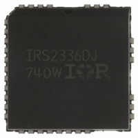
IRS2336DJTRPBF International Rectifier, IRS2336DJTRPBF Datasheet - Page 32

IRS2336DJTRPBF
Manufacturer Part Number
IRS2336DJTRPBF
Description
IC GATE DRIVER HV 3PHASE 44-PLCC
Manufacturer
International Rectifier
Datasheet
1.IRS23364DSTRPBF.pdf
(47 pages)
Specifications of IRS2336DJTRPBF
Configuration
3 Phase Bridge
Input Type
Differential
Delay Time
530ns
Current - Peak
200mA
Number Of Configurations
1
Number Of Outputs
3
High Side Voltage - Max (bootstrap)
600V
Voltage - Supply
10 V ~ 20 V
Operating Temperature
-40°C ~ 125°C
Mounting Type
Surface Mount
Package / Case
44-PLCC (32 Leads)
Lead Free Status / RoHS Status
Lead free / RoHS Compliant
Other names
IRS2336DJTRPBFTR
Available stocks
Company
Part Number
Manufacturer
Quantity
Price
Company:
Part Number:
IRS2336DJTRPBF
Manufacturer:
International Rectifier
Quantity:
10 000
IRS2336x(D) Family
Figure 30: Parasitic Elements
Figure 31: V
positive
Figure 32: V
negative
S
S
In a typical motor drive system, dV/dt is typically designed to be in the range of 3-5 V/ns. The negative V
transient
S
voltage can exceed this range during some events such as short circuit and over-current shutdown, when di/dt is
greater than in normal operation.
International Rectifier’s HVICs have been designed for the robustness required in many of today’s demanding
applications. The IRS2336xD has been seen to withstand large negative V
transient conditions on the order of -50 V
S
for a period of 50 ns. An illustration of the IRS2336D’s performance can be seen in Figure 33. This experiment was
conducted using various loads to create this condition; the curve shown in this figure illustrates the successful
operation of the IRS2336D under these stressful conditions. In case of -V
transients greater then -20 V for a period
S
of time greater than 100 ns; the HVIC is designed to hold the high-side outputs in the off state for 4.5 s in order to
ensure that the high- and low-side power switches are not on at the same time.
Figure 33: Negative V
transient results for an International Rectifier HVIC
S
Even though the IRS2336xD has been shown able to handle these large negative V
transient conditions, it is highly
S
recommended that the circuit designer always limit the negative V
transients as much as possible by careful PCB
S
layout and component use.
PCB Layout Tips
Distance between high and low voltage components: It’s strongly recommended to place the components tied to the
floating voltage pins (V
and V
) near the respective high voltage portions of the device. The IRS2336xD in the
B
S
PLCC44 package has had some unused pins removed in order to maximize the distance between the high voltage
and low voltage pins. Please see the Case Outline PLCC44 information in this datasheet for the details.
www.irf.com
© 2009 International Rectifier
32


