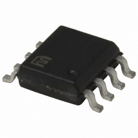
MIC5014YM Micrel Inc, MIC5014YM Datasheet - Page 8

MIC5014YM
Manufacturer Part Number
MIC5014YM
Description
IC DRIVER MOSF HI/LOW SIDE 8SOIC
Manufacturer
Micrel Inc
Datasheet
1.MIC5014YM_TR.pdf
(12 pages)
Specifications of MIC5014YM
Configuration
High or Low Side
Input Type
Non-Inverting
Delay Time
2.5ms
Number Of Configurations
1
Number Of Outputs
1
Voltage - Supply
2.75 V ~ 30 V
Operating Temperature
-40°C ~ 85°C
Mounting Type
Surface Mount
Package / Case
8-SOIC (3.9mm Width)
Device Type
High Side / Low Side
Module Configuration
High Side / Low Side
Input Delay
2.5ms
Output Delay
6µs
Supply Voltage Range
2.75V To 30V
Driver Case Style
SOIC
No. Of Pins
8
Number Of Drivers
1
Driver Configuration
Non-Inverting
Driver Type
High Side/Low Side
Input Logic Level
TTL
Operating Supply Voltage (max)
30V
Operating Supply Voltage (min)
2.75V
Turn Off Delay Time
30us
Turn On Delay Time (max)
8ms
Operating Temp Range
-40C to 85C
Operating Temperature Classification
Industrial
Mounting
Surface Mount
Pin Count
8
Package Type
SOIC
Lead Free Status / RoHS Status
Lead free / RoHS Compliant
Current - Peak
-
High Side Voltage - Max (bootstrap)
-
Lead Free Status / Rohs Status
Compliant
Other names
576-2352
MIC5014YM
MIC5014YM
Available stocks
Company
Part Number
Manufacturer
Quantity
Price
Company:
Part Number:
MIC5014YM
Manufacturer:
MICREL
Quantity:
179
Part Number:
MIC5014YM
Manufacturer:
MIC
Quantity:
20 000
MIC5014/5015
nation of an MIC5014/5015 and a power FET makes an
effective driver for a standard incandescent or halogen lamp
load. Such loads often have high inrush currents, as the
resistance of a cold filament is less than one-tenth as much as
when it is hot. Power MOSFETs are well suited to this
application as they have wider safe operating areas than do
power bipolar transistors. It is important to check the SOA
curve on the data sheet of the power FET to be used against
the estimated or measured inrush current of the lamp in
question prior to prototyping to prevent “explosive” results.
If overcurrent sense is to be used, first measure the duration
of the inrush, then use the topology of Figure 5 with the RC of
the timer chosen to accomodate the duration with suitable
guardbanding.
Relay Driver (Figure 9) Some power relay applications re-
quire the use of a separate switch or drive control, such as in
the case of microprocessor control of banks of relays where
a logic level control signal is used, or for drive of relays with
high power requirements. The combination of an MIC5014/
5015 and a power FET also provides an elegant solution to
power relay drive.
MIC5014/5015
Incandescent/Halogen Lamp Driver (Figure 8) The combi-
OFF
ON
Control Input
OFF
ON
10µF
Control Input
10µF
Figure 8. Halogen Lamp Driver
Figure 9: Relay Driver
1
2
3
4
V+
Input
Source
Gnd
1
2
3
4
V+
Input
Source
Gnd
MIC5014
MIC5014
Gate
NC
NC
NC
Gate
NC
NC
NC
HLX64623
8
7
6
5
OSRAM
8
7
6
5
12V
IRF540
12V
IRF540
Guardian Electric
1725-1C-12D
8
Motor Driver With Stall Shutdown (Figure 10) Tachometer
feedback can be used to shut down a motor driver circuit when
a stall condition occurs. The control switch is a 3-way type; the
“START” position is momentary and forces the driver ON.
When released, the switch returns to the “RUN” position, and
the tachometer’s output is used to hold the MIC5014 input ON.
If the motor slows down, the tach output is reduced, and the
MIC5014 switches OFF. Resistor “R” sets the shutdown
threshold.
Simple DC-DC Converter (Figure 11) The simplest applica-
tion for the MIC5014 is as a basic one-chip DC-DC converter.
As the output (Gate) pin has a relatively high impedance, the
output voltage shown will vary significantly with applied load.
10µF
R
330kΩ
Figure 10. Motor Stall Shutdowm
1N4148
Figure 11. DC - DC Converter
330kΩ
5V
1
2
3
4
V+
Input
Source
Gnd
1
2
3
4
MIC5014
V+
Input
Source
Gnd
MIC5014
T
Gate
NC
NC
NC
Gate
NC
NC
NC
8
7
6
5
10µF
8
7
6
5
V
OUT
12V
= 12V
M
IRFZ44
Micrel, Inc.
June 2005


