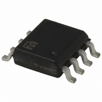
MIC4424YM TR Micrel Inc, MIC4424YM TR Datasheet - Page 10

MIC4424YM TR
Manufacturer Part Number
MIC4424YM TR
Description
IC DRIVER MOSFET 3A DUAL 8-SOIC
Manufacturer
Micrel Inc
Datasheet
1.MIC4424YM_TR.pdf
(13 pages)
Specifications of MIC4424YM TR
Configuration
Low-Side
Input Type
Non-Inverting
Delay Time
33ns
Current - Peak
3A
Number Of Configurations
2
Number Of Outputs
2
Voltage - Supply
4.5 V ~ 18 V
Operating Temperature
-40°C ~ 85°C
Mounting Type
Surface Mount
Package / Case
8-SOIC (3.9mm Width)
Number Of Drivers
2
Driver Configuration
Non-Inverting
Driver Type
Low Side
Input Logic Level
CMOS/TTL
Rise Time
35ns
Fall Time
35ns
Propagation Delay Time
75ns
Operating Supply Voltage (max)
18V
Peak Output Current
3mA
Output Resistance
3.5Ohm
Operating Supply Voltage (min)
4.5V
Operating Temp Range
-40C to 85C
Operating Temperature Classification
Industrial
Mounting
Surface Mount
Pin Count
8
Package Type
SOIC
Lead Free Status / RoHS Status
Lead free / RoHS Compliant
High Side Voltage - Max (bootstrap)
-
Lead Free Status / Rohs Status
Compliant
Other names
576-1546-2
MIC4424YMTR
MIC4424YMTR
MIC4424YMTR
MIC4424YMTR
MIC4423/4424/4425
Then quiescent power loss:
Total power dissipation, then, is:
Assuming an SOIC package, with an θ
result in the junction running at:
above ambient, which, given a maximum ambient tempera-
ture of 60°C, will result in a maximum junction temperature
of 89.4°C.
EXAMPLE 2: A MIC4424 operating on a 15V input, with one
driver driving a 50Ω resistive load at 1MHz, with a duty cycle
of 67%, and the other driver quiescent, in a maximum ambi-
ent temperature of 40°C:
First, I
Given R
and:
(because only one side is operating)
and:
(this assumes that the unused side of the driver has its input
grounded, which is more efficient)
MIC4423/4424/4425
O
must be determined.
0.2454 x 120 = 29.4°C
P
I
I
= (1,000,000 x 15 x 3.3 x 10
= 0.025 W
P
= 0.015W
P
P
O
I
P
P
O
O
O
Q
L
Q
D
from the characteristic curves then,
T
L
= V
= 15 / (3.3 + 50)
= 0.281A
= I
= 15 x [(0.67 x 0.00125) + (0.33 x 0.000125) +
= V
= 12 x [(0.5 x 0.0035) + (0.5 x 0.0003)]
= 0.0228W
= 0.2160 + 0.0066 + 0.0228
= 0.2454W
= (0.281)
= 0.174W
= F x V
2
S
(1 x 0.000125)]
x R
/ (R
S
x [D x I
O
O
x D
S
+ R
x (A•s)/2
2
x 3.3 x 0.67
LOAD
H
+ (1 – D) x I
)
–9
) / 2
JA
L
]
of 120°C/W, this will
10
then:
In a ceramic package with an θ
power results in a junction temperature given the maximum
40°C ambient of:
The actual junction temperature will be lower than calculated
both because duty cycle is less than 100% and because the
graph lists R
will be somewhat lower.
Definitions
P
P
C
P
P
R
V
D = Duty Cycle expressed as the fraction of time the input
I
I
I
H
D
D
Q
L
L
L
T
f = Operating Frequency of the driver in Hertz
O
S
= Output resistance of a driver in Ohms.
= Load Capacitance in Farads.
= Power supply current drawn by a driver when both
= Power supply current drawn by a driver when both
= Output current from a driver in Amps.
= Total power dissipated in a driver in Watts.
= Power dissipated in the driver due to the driver’s
= Power dissipated in a quiescent driver in Watts.
= Power dissipated in a driver when the output
= Power supply voltage to the IC in Volts.
(0.213 x 100) + 40 = 61.4°C
to the driver is high.
inputs are high and neither output is loaded.
load in Watts.
changes states (“shoot-through current”) in Watts.
NOTE: The “shoot-through” current from a dual
transition (once up, once down) for both drivers is
stated in the graph on the following page in ampere-
nanoseconds. This figure must be multiplied by the
number of repetitions per second (frequency to find
Watts).
P
inputs are low and neither output is loaded.
D
= 0.174 + 0.025 + 0.0150
= 0.213W
DS(on)
at a T
J
of 125°C and the R
JA
of 100°C/W, this amount of
DS(on)
Micrel, Inc.
at 61°C T
July 2005
J


