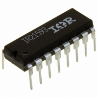
IR21593 International Rectifier, IR21593 Datasheet - Page 14

IR21593
Manufacturer Part Number
IR21593
Description
IC CTRLR BALLAST DIMMING 16-DIP
Manufacturer
International Rectifier
Type
Ballast Controllerr
Datasheet
1.IR21592SPBF.pdf
(26 pages)
Specifications of IR21593
Frequency
30 ~ 230 kHz
Current - Supply
10mA
Voltage - Supply
12.5 V ~ 15.6 V
Operating Temperature
-40°C ~ 125°C
Package / Case
16-DIP (0.300", 7.62mm)
Lead Free Status / RoHS Status
Contains lead / RoHS non-compliant
Current - Output
-
Other names
*IR21593
Available stocks
Company
Part Number
Manufacturer
Quantity
Price
Company:
Part Number:
IR21593
Manufacturer:
PHILIPS
Quantity:
3 130
Part Number:
IR21593
Manufacturer:
IR
Quantity:
20 000
Part Number:
IR21593S
Manufacturer:
IR
Quantity:
20 000
Company:
Part Number:
IR21593SPBF
Manufacturer:
IR
Quantity:
560
Company:
Part Number:
IR21593STRPBF
Manufacturer:
FSC
Quantity:
1 001
IR21592/IR21593
Phase Control
To understand phase control, a simplified model
for the ballast output stage is used (Figure 1). The
lamp and filaments are replaced with resistors,
with the lamp inserted between the filament
resistors (R1, R2, R3 and R4).
During preheat and ignition (Figure 2), the circuit
is a high-Q series LC with a strong input current to
input voltage phase inversion from +90 to -90
degrees at the resonance frequency. For operating
frequencies slightly above resonance and higher,
the phase is fixed at -90 degrees for the duration
of preheat and ignition. During dimming, the circuit
is an L in series with a parallel R and C, with a
weak phase inversion at high lamp power and a
strong phase inversion at low lamp power.
14
Figure 1, Dimming ballast output stage.
Vin
Functional Description
L
Rlamp
R1
R3
R2
R4
( S ) & ( PbF )
C
In the time domain (Figure 3), the input current is
shifted -90 degrees from the input half-bridge
voltage during preheat and ignition, and
somewhere between 0 and -90 degrees after
ignition during running. Zero phase-shift
corresponds to maximum power.
When the phase is calculated and plotted versus
lamp power (Figure 4), the result is a linear dimming
curve, even down to ultra-low light levels where
the resistance of the lamp can change by orders
of magnitude.
Figure 2, Typical output stage transfer function for
Figure 3, Typical ballast output stage waveforms.
-10
-20
-30
0
20
10
0
5
n
n
run
10
ph/ign
different lamp power levels.
V
in
I
in run
15
100%
20
50%
Frequency [kHz]
25
10%
30
10%
100%
50%
PH/IGN
I
in
PH/IGN
35
ph/ign
40
www.irf.com
45
50
400
350
300
250
200
150
100
50
0
-50
-100
t


