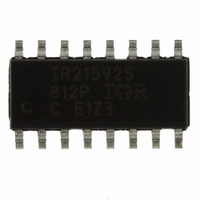
IR21592SPBF International Rectifier, IR21592SPBF Datasheet - Page 3

IR21592SPBF
Manufacturer Part Number
IR21592SPBF
Description
IC CNTRLR BALLAST DIMMING 16SOIC
Manufacturer
International Rectifier
Type
Ballast Controllerr
Datasheet
1.IR21592SPBF.pdf
(26 pages)
Specifications of IR21592SPBF
Frequency
73 ~ 108 kHz
Current - Supply
10mA
Voltage - Supply
12.5 V ~ 15.6 V
Operating Temperature
-40°C ~ 125°C
Package / Case
16-SOIC (3.9mm Width)
Package
16-lead SOIC Narrow
Circuit
Fluorescent Ballast IC
Offset Voltage (v)
600
Output Source Current Min (ma)
null
Output Sink Current Min (ma)
null
Vcc Range (v)
12-25V with UVLO
Output Voltage Min (v)
10
Output Voltage Max (v)
20
Pbf
PbF Option Available
For Use With
IRPLDIM2U - BALLAST DIM DIG 32W/T8 120VAC
Lead Free Status / RoHS Status
Lead free / RoHS Compliant
Current - Output
-
Note 2:
Note 3:
www.irf.com
Recommended Operating Conditions
For proper operation the device should be used within the recommended conditions.
Electrical Characteristics
V
R
Supply Characteristics
I
I
I
I
Symbol Definition
V
V
I
I
V
QCCUV
QCCFLT
CCFMIN
CCFMAX
CC
CCFMIN
CCFMAX
Symbol
MIN
CCUV+
CCHYS
CLAMP
V
R
V
V
V
V
V
V
= V
I
BSMIN
I
I
V
VCO
FMIN
MAX
T
CC
= 56k, V
DIM
MIN
SD
CS
CC
BS
S
J
BS
Enough current should be supplied into the VCC lead to keep the internal 15.6V zener clamp diode on this lead
regulating its voltage, V
The MAX lead is a voltage-controlled current source. For optimum dim interface current mirror performance,
this current should be kept between 0 and 750 A.
= V
V
threshold
V
V
V
V
V
V
UVLO mode quiescent current
Fault-mode quiescent current
CPH
BIAS
CC
CC
CC
CC
CC
CC
CC
Definition
High side floating supply voltage
Steady state high side floating supply offset voltage
Supply voltage
Supply current
VCO pin voltage
DIM pin voltage
MAX pin current (note 3)
MIN pin voltage
Minimum required V
Minimum frequency setting resistance
Shutdown pin current
Current sensing pin current
Junction temperature
supply undervoltage lockout hysteresis
supply undervoltage positive going
zener shunt clamp voltage
= 0.0V, C
supply current @ FMAX (IR21592)
supply current @ FMAX (IR21593)
supply current @ FMIN (IR21592)
supply current @ FMIN (IR21593)
= 14V +/- 0.25V, V
LO,HO
CLAMP
= 1000pF, T
BS
CS
.
voltage for proper HO functionality
= 0.5V, V
A
= 25
SD
o
= 0.0V, R
C unless otherwise specified.
Min.
12.0
14.5
1.5
70
—
—
—
—
—
FMIN
IR21592/IR21593
= 40k, C
Typ.
12.5
1.6
200
240
5.6
6.0
5.4
6.8
15.6
VCO
Max.
16.5
= 10 nF, V
330
13.0
1.7
—
—
—
—
—
V
V
CC
note 2
Min.
CCUV+
-750
0.5
-40
10
—
-1
-1
-1
0
1
- 0.7
Units
DIM
mA
V
V
A
= 0.0V, R
V
CLAMP (15.6)
V
Max.
Test Conditions
CLAMP
V
SD=5V, CS=2V, or
Tj > T
V
V
V
V
I
100
125
600
5.0
CC
( S ) & ( PbF )
10
0
3
1
1
5
CC
VCO
VCO
VCO
VCO
5
MAX
= 10mA
= 10V
SD
= 0V
= 5V
= 0V
= 5V
= 33k,
Units
mA
mA
k
V
o
V
V
C
A
3


