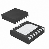
MAX4990ETD+T Maxim Integrated Products, MAX4990ETD+T Datasheet - Page 5

MAX4990ETD+T
Manufacturer Part Number
MAX4990ETD+T
Description
IC EL LAMP DRIVER ESD 14-TDFN
Manufacturer
Maxim Integrated Products
Type
EL Lamp Driverr
Datasheet
1.MAX4990ETDT.pdf
(8 pages)
Specifications of MAX4990ETD+T
Frequency
210 ~ 290 kHz
Current - Supply
350µA
Voltage - Supply
2.4 V ~ 5.5 V
Operating Temperature
-40°C ~ 85°C
Package / Case
14-TDFN Exposed Pad
Lead Free Status / RoHS Status
Lead free / RoHS Compliant
Current - Output
-
Lead Free Status / Rohs Status
Details
Other names
MAX4990ETD+T
MAX4990ETD+TTR
MAX4990ETD+TTR
When the f
lamp frequency is f
dual CMOS timer (U2) to generate a 50% duty-cycle
square wave. The VR3 value can be adjusted while
power is applied (see Table 6).
ICM7556 square-wave frequency f
The boost converter switching frequency can be set by
an external capacitor, C
Table 6. Lamp Output Frequency When JU4 = Pins 1-2 (External f
CW = Clockwise. Approximate trimmer values provided for initial guidance only.
Table 7. Boost Converter Frequency When JU5 = Open (Internal f
CW = Clockwise. Approximate trimmer values provided for initial guidance only.
Table 8. Boost Converter Frequency When JU5 = Pins 1-2 (External f
Note: f SW square wave has fixed duty cycle = (R6 + R7)/(R7 + 2 x R6) = 90%. Approximate trimmer values provided for initial guid-
ance only.
T IM IN G C A PAC IT OR ( p F )
C7 = 15000
C
ICM7556
C3 = 68
SW
Center: 90° or 270°
EL
(pF)
VC1 TRIMMER
Maximum: 180°
Minimum: 0°
pin is driven by an external clock, the
f
SW
_______________________________________________________________________________________
EL
Boost Converter Frequency
=
/4. The EV kit uses an ICM7556
R
SW
JU1 SHUNT POSITION
SLEW
Lamp Output Frequency
(see Table 7).
3 61
(External f
.
TRIMMER
100% CW
×
50% CW
0% CW
C
VR3
1-2
2-3
SW
EL
= 1/(1.4 x R x C).
(R
SLEW
EL
TIMING CAPACITOR (pF)
Signal)
, C
(50 ≤ VC1 ≤ 100) + 25
RESISTORS (kΩ)
VR3 + R5 = 513.3
VR3 + R5 = 263.3
ICM7556 TIMING
VR3 + R5 = 13.3
SW
VR1 TRIMMER
VC1 = 30 + 25
VC1 = 7 + 25
25% CW
50% CW
ICM7556
)
—
MAX4990 Evaluation Kit
Boost converter switching frequency can be driven by
an external clock. The EV kit uses an ICM7556 dual
CMOS timer (U2) to generate a 90% duty-cycle square-
wave pulse. The C
power is applied (see Table 8).
f
EL
VR1 + R1 = 0.560
VR1 + R1 = 0.997
FROM ICM7556
R2 = 0.374
0.0927
R
0.180
(kHz)
(MΩ)
3.58
SLEW
Boost Converter Frequency
= 1.44/((R7 + 2 x R6) x (VC1)) (kHz)
SW
f
SW
value can be adjusted while
EL
SW
= ICM7556 SQUARE WAVE
)
)
(External f
SW
)
LAMP FREQUENCY =
112
60
33
f
f
EL
SW
SW
895
142
/4 (Hz)
23
45
95
53
(kHz)
Signal)
5


