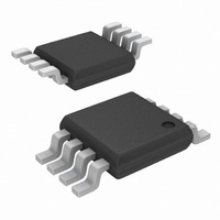
EL1848IY Intersil, EL1848IY Datasheet - Page 9

EL1848IY
Manufacturer Part Number
EL1848IY
Description
IC LED DRIVR WHITE BCKLGT 8-MSOP
Manufacturer
Intersil
Type
Backlight, White LEDr
Datasheet
1.EL1848IWT-T7.pdf
(12 pages)
Specifications of EL1848IY
Constant Current
Yes
Topology
PWM, Step-Up (Boost)
Number Of Outputs
1
Internal Driver
Yes
Type - Primary
Backlight
Type - Secondary
White LED
Frequency
800kHz ~ 1.2MHz
Voltage - Supply
2.6 V ~ 13.2 V
Voltage - Output
14V
Mounting Type
Surface Mount
Package / Case
8-MSOP, Micro8™, 8-uMAX, 8-uSOP,
Operating Temperature
-40°C ~ 85°C
Current - Output / Channel
90mA
Internal Switch(s)
Yes
Efficiency
91%
Lead Free Status / RoHS Status
Contains lead / RoHS non-compliant
Detailed Description
The EL1848 is a constant current boost regulator specially
designed for driving white LEDs. It can drive up to 3 LEDs in
series or 9 LEDs in parallel/series configuration and
achieves efficiency up to 91%.
The brightness of the LEDs is adjusted through a voltage
level on the CNTL pin. When the level falls below 0.1V, the
chip goes into shut-down mode and consumes less than
1µA of current for V
Steady-State Operation
EL1848 is operated in constant frequency PWM. The
switching is around 1MHz. Depending on the input voltage,
the inductance, the type of LEDs driven, and the LED’s
current, the converter operates at either continuous
conduction mode or discontinuous conduction mode (see
waveforms). Both are normal.
Brightness Control
LED’s current is controlled by the voltage level on CNTL pin
(V
with frequency less than 200Hz (for C
higher frequency PWM is used, an RC filter is recommended
before the CNTL pin (see Figure 17).
The relationship between the LED current and CNTL voltage
level is as follows:
When R
15mA. The range of V
Shut-Down
When V
down mode. The max current consumed by the chip is less
than 1µA for V
Over-Voltage Protection
When an LED string is disconnected from the output, V
continue to rise because of no current feedback. When V
reaches 14V (nominal), the chip will shut down. The output
voltage will drop. When V
chip will boost output voltage again until it reaches 14V. This
I
LED
CNTL
=
). This voltage can be either a DC or a PWM signal
----------------------------
13.33 R
CNTL
1
V
FIGURE 19. PWM BRIGHTNESS CONTROL
is 5Ω, 1V of V
CNTL
SIGNAL
×
is less than 100mV, the converter is in shut-
PWM
IN
1
less than 5.5V.
IN
CNTL
less than 5.5V.
100K
0.1µF
CNTL
O
drops below 11V (nominal), the
is 250mV to 5.5V.
conveniently sets I
9
3
CNTL
COMP
=4700pF). When a
LED
to
O
will
O
EL1848
hiccough continues until LED is applied or converter is shut
down.
When designing the converter, caution should be taken to
ensure the highest operating LED voltage does not exceed
13V, the minimum shut-down voltage. There is no external
component required for this function.
Component Selection
The input and output capacitors are not very important for
the converter to operate normally. The input capacitance
is normally 0.22µF - 4.7µF and output capacitance
0.22µF - 1µF. Higher capacitance is allowed to reduce the
voltage/current ripple, but at added cost. Use X5R or X7R
type (for its good temperature characteristics) of ceramic
capacitors with correct voltage rating and maximum height.
When choosing an inductor, make sure the inductor can
handle the average and peak currents giving by following
formulas (80% efficiency assumed):
where:
• ∆I
• L inductance in µH
• FS switching frequency, typical 1MHz
A wide range of inductance (6.8µH - 68µH) can be used for
the converter to function correctly. For the same series of
inductors, the lower inductance has lower DC resistance
(DCR), which has less conducting loss. But the ripple current
is bigger, which generates more RMS current loss. Figure 9
shows the efficiency of the demo board under different
inductance for a specific series of inductor. For optimal
efficiency in an application, it is a good exercise to check
several adjacent inductance values of your preferred series
of inductors.
I
I
∆I
LAVG
LPK
L
L
=
=
is the peak-to-peak inductor current ripple in Ampere
V
-------------------------------------------- -
=
I
IN
LAVG
L
----------------------- -
0.8 V
I
×
O
×
(
V
×
×
V
O
+
V
O
×
O
IN
1
-- -
2
–
F
×
V
S
∆I
IN
L
)


