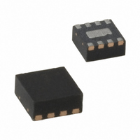
MIC2287-34BML TR Micrel Inc, MIC2287-34BML TR Datasheet - Page 5

MIC2287-34BML TR
Manufacturer Part Number
MIC2287-34BML TR
Description
IC LED DRIVER WHITE BCKLGT 8-MLF
Manufacturer
Micrel Inc
Type
Backlight, White LEDr
Datasheet
1.MIC2287-24YML_TR.pdf
(10 pages)
Specifications of MIC2287-34BML TR
Constant Current
Yes
Topology
PWM, Step-Up (Boost)
Number Of Outputs
1
Internal Driver
Yes
Type - Primary
Backlight, Flash/Torch
Type - Secondary
White LED
Frequency
1.05MHz ~ 1.35MHz
Voltage - Supply
2.5 V ~ 10 V
Mounting Type
Surface Mount
Package / Case
8-MLF®, QFN
Operating Temperature
-40°C ~ 125°C
Current - Output / Channel
20mA
Internal Switch(s)
Yes
Lead Free Status / RoHS Status
Contains lead / RoHS non-compliant
Voltage - Output
-
Efficiency
-
Other names
MIC2287-34BMLTR
MIC2287-34BMLTR
MIC2287-34BMLTR
Functional Diagram
Functional Description
The MIC2287 is a constant frequency, PWM current mode
boost regulator. The block diagram is shown above. The
MIC2287 is composed of an oscillator, slope compensation
ramp generator, current amplifier, g
generator, and a 500mA bipolar output transistor. The oscil-
lator generates a 1.2MHz clock. The clock’s two functions
are to trigger the PWM generator that turns on the output
transistor and to reset the slope compensation ramp genera-
tor. The current amplifier is used to measure the switch cur-
rent by amplifying the voltage signal from the internal sense
resistor. The output of the current amplifier is summed with
the output of the slope compensation ramp generator. This
summed current-loop signal is fed to one of the inputs of the
PWM generator.
July 2005
MIC2287
*
OVP available on MLF
V
VIN
REF
95mV
FB
m
OVP*
error amplifier, PWM
OVP*
g
TM
m
package option only
Oscillator
1.2MHz
MIC2287 Block Diagram
5
The g
external sense resistor and amplifies the error between the
detected signal and the 95mV reference voltage. The output
of the g
that is fed to the other input of the PWM generator. When
the current-loop signal exceeds the voltage-loop signal, the
PWM generator turns off the bipolar output transistor. The
next clock period initiates the next switching cycle, maintain-
ing the constant frequency current-mode PWM control. The
LED is set by the feedback resistor:
The Enable pin shuts down the output switching and disables
control circuitry to reduce input current-to-leakage levels.
Enable pin input current is zero at zero volts.
Generator
Generator
Ramp
PWM
EN
S
m
I
LED
error amplifier measures the LED current through the
m
=
error amplifier provides the voltage-loop signal
95mv
R
FB
SW
GND
M9999-070105
Micrel, Inc.


