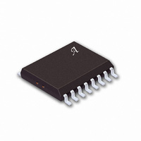
A6275ELWTR Allegro Microsystems Inc, A6275ELWTR Datasheet - Page 11

A6275ELWTR
Manufacturer Part Number
A6275ELWTR
Description
IC LED DRIVER LINEAR 16-SOIC
Manufacturer
Allegro Microsystems Inc
Type
Linear (Non-Switching)r
Datasheet
1.A6275SLWTR-T.pdf
(12 pages)
Specifications of A6275ELWTR
Constant Current
Yes
Topology
8-Bit Shift Register
Number Of Outputs
8
Internal Driver
Yes
Type - Primary
General Purpose
Frequency
20MHz
Voltage - Supply
4.5 V ~ 5.5 V
Voltage - Output
1V
Mounting Type
Surface Mount
Package / Case
16-SOIC (0.300", 7.5mm Width)
Operating Temperature
-40°C ~ 85°C
Current - Output / Channel
75.5mA
Internal Switch(s)
Yes
Lead Free Status / RoHS Status
Contains lead / RoHS non-compliant
Efficiency
-
Available stocks
Company
Part Number
Manufacturer
Quantity
Price
Part Number:
A6275ELWTR
Manufacturer:
ALLEGRO/雅丽高
Quantity:
20 000
The load current per bit (I
(R
Package Power Dissipation (P
low able package power dissipation is determined as
The actual package power dissipation is
When the load supply voltage is greater than 3 V to 5 V,
considering the package power dissipating limits of these
devices, or if P
ducer (V
Load Supply Voltage (V
signed to operate with driver voltage drops (V
0.4 V to 0.7 V with LED forward voltages (V
4.0 V. If higher voltages are dropped across the driver,
package power dissipation will be increased signifi cantly.
To minimize package power dissipation, it is rec om -
mend ed to use the lowest possible load supply voltage or
to set any series dropping voltage (V
with V
diode (V
A6275
EXT
100
80
60
40
20
) as shown in the fi gure below.
0
100
DROP
P
DROP
Z
), or a series string of diodes (approximately
D
CURRENT-CONTROL RESISTANCE, R
(act) = dc(V
= I
) should be used.
o
D
200
P
(act) > P
× R
V
D
(max) = (150 - T
DROP
DROP
300
CE
= V
D
for a single driver, or a Zener
O
(max), an external voltage re-
500
× I
) is set by the external re sis tor
LED
LED
O
700
× 8) + (V
). These devices are de-
- V
Serial-Input Constant-Current Latched LED Driver
F
A
D
1 k
)/R
DROP
- V
). The maximum al-
θJA
with Open LED Detection and Dot Correction
CE
DD
EXT
V
) as
CE
.
IN OHMS
= 0.7 V
× I
2 k
Applications Information
F
CE
) of 1.2 V to
DD
) of
).
3 k
Dwg. GP-061
5 k
0.7 V per diode) for a group of drivers. If the available
voltage source will cause unacceptable dissipation and
series resistors or diode(s) are undesirable, a regulator
such as the Sanken Series SAI or Series SI can be used to
pro vide supply voltages as low as 3.3 V.
For reference, typical LED forward voltages are:
Pattern Layout. This device has a common logic-ground
and power-ground terminal. If ground pattern layout
con tains large common-mode resistance, and the voltage
between the system ground and the LATCH ENABLE or
CLOCK terminals ex ceeds 2.5 V (because of switching
noise), these devices may not operate correctly.
V
V CE
V DROP
V F
LED
White
Blue
Green
Yellow
Amber
Red
Infrared
115 Northeast Cutoff
1.508.853.5000; www.allegromicro.com
Allegro MicroSystems, Inc.
Worcester, Massachusetts 01615-0036 U.S.A.
1.9 – 2.65 V
1.6 – 2.25 V
3.5 – 4.0 V
3.0 – 4.0 V
1.8 – 2.2 V
2.0 – 2.1 V
1.2 – 1.5 V
Dwg. EP-064
10


