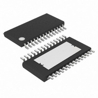
MAX16807AUI+T Maxim Integrated Products, MAX16807AUI+T Datasheet - Page 6

MAX16807AUI+T
Manufacturer Part Number
MAX16807AUI+T
Description
IC LED DRVR WT/RGB BCKLT 28TSSOP
Manufacturer
Maxim Integrated Products
Type
Backlight, White LED, RGB (Serial Interface)r
Datasheet
1.MAX16807AUIT.pdf
(19 pages)
Specifications of MAX16807AUI+T
Constant Current
Yes
Topology
Open Drain, PWM, Step-Down (Buck), SEPIC, Step-Up (Boost)
Number Of Outputs
8
Internal Driver
Yes
Type - Primary
Backlight
Type - Secondary
RGB, White LED
Frequency
20kHz ~ 1MHz
Voltage - Supply
8 V ~ 26.5 V
Voltage - Output
36V
Mounting Type
Surface Mount
Package / Case
28-TSSOP Exposed Pad, 28-eTSSOP, 28-HTSSOP
Operating Temperature
-40°C ~ 125°C
Current - Output / Channel
55mA
Internal Switch(s)
No
Operating Supply Voltage
3 V to 5.5 V
Maximum Supply Current
5 mA
Maximum Power Dissipation
2162 mW
Maximum Operating Temperature
+ 125 C
Mounting Style
SMD/SMT
Minimum Operating Temperature
- 40 C
Lead Free Status / RoHS Status
Lead free / RoHS Compliant
Efficiency
-
Lead Free Status / Rohs Status
Details
Integrated 8-Channel LED Driver with
Switch-Mode Boost and SEPIC Controller
3.3V TIMING CHARACTERISTICS
(V+ = +3V to < +4.5V, V
to +125°C, unless otherwise noted. Typical values are at T A = +25°C.) (Notes 1, 5)
6
Note 1: All devices are 100% production tested at T
Note 2: Guaranteed by design, not production tested.
Note 3: Parameter is measured at trip point of latch with V
Note 4: Gain is defined as A = ∆V
Note 5: See Figures 3 and 4.
Note 6: A 65Ω pullup resistor is connected from OUT_ to 5.5V. Rising refers to V
INTERFACE TIMING CHARACTERISTICS
CLK Clock Period
CLK Pulse-Width High
CLK Pulse-Width Low
DIN Setup Time
DIN Hold Time
DOUT Propagation Delay
DOUT Rise Time
DOUT Fall Time
LE Pulse-Width High
LE Setup Time
LE Rising to OUT_ Rising Delay
LE Rising to OUT_ Falling Delay
CLK Rising to OUT_ Rising Delay
CLK Rising to OUT_ Falling Delay
OE Rising to OUT_ Rising Delay
OE Falling to OUT_ Falling Delay
OUT_ Turn-On Fall Time
OUT_ Turn-Off Rise Time
_______________________________________________________________________________________
falling refers to V
PARAMETERS
AGND
OUT_
= V
when current through OUT_ is turned on.
PGND
COMP
SYMBOL
= 0V; all voltages are measured with respect to PGND, unless otherwise noted. T A = T J = -40°C
t
t
t
t
/∆V
t
t
t
t
t
t
t
t
t
CRR
CRF
OER
OEF
t
t
t
LRR
LRF
DO
CP
CH
DS
DH
DR
LW
t
CL
DF
LS
t
R
F
CS
, 0.05V ≤ V
C
C
(Note 6)
(Note 6)
(Note 6)
(Note 6)
(Note 6)
(Note 6)
80% to 20% (Note 6)
20% to 80% (Note 6)
DOUT
DOUT
J
= +25°C and T
CS
= 10pF, 20% to 80%
= 10pF, 80% to 20%
FB
≤ 0.25V.
= 0V.
CONDITIONS
J
= +125°C. Limits to T
OUT_
when current through OUT_ is turned off and
A
= -40°C are guaranteed by design.
MIN
52
24
24
12
20
15
4
8
TYP
MAX
140
350
140
350
140
350
275
150
70
12
12
UNITS
ns
ns
ns
ns
ns
ns
ns
ns
ns
ns
ns
ns
ns
ns
ns
ns
ns
ns


