MAX6968AUE+ Maxim Integrated Products, MAX6968AUE+ Datasheet - Page 7
MAX6968AUE+
Manufacturer Part Number
MAX6968AUE+
Description
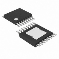
IC LED DRIVER LINEAR 16-TSSOP
Manufacturer
Maxim Integrated Products
Type
Linear (Serial Interface)r
Datasheet
1.MAX6968APE.pdf
(13 pages)
Specifications of MAX6968AUE+
Constant Current
Yes
Topology
8-Bit Shift Register, Open Drain, PWM
Number Of Outputs
8
Internal Driver
Yes
Type - Primary
General Purpose
Voltage - Supply
3 V ~ 5.5 V
Voltage - Output
5.5V
Mounting Type
Surface Mount
Package / Case
16-TSSOP Exposed Pad, 16-eTSSOP, 16-HTSSOP
Operating Temperature
-40°C ~ 125°C
Current - Output / Channel
55mA
Internal Switch(s)
No
Number Of Segments
16
Low Level Output Current
60 mA
Operating Supply Voltage
3 V to 5.5 V
Maximum Supply Current
25 mA
Maximum Power Dissipation
1702 mW
Maximum Operating Temperature
+ 85 C
Mounting Style
SMD/SMT
Minimum Operating Temperature
- 40 C
Lead Free Status / RoHS Status
Lead free / RoHS Compliant
Frequency
-
Efficiency
-
Lead Free Status / Rohs Status
Details


The MAX6968 LED driver comprises a 4-wire serial
interface driving eight constant-current sinking open-
drain output ports. The outputs drive LEDs in either
static or multiplex applications (Figure 1). The constant-
current outputs are guaranteed for current accuracy
not only with chip-supply voltage variations (5V ±10%
and 3V to 5.5V), but also over a realistic range of driver
output voltage drop (0.5V to 2.5V). The drivers use cur-
rent-sensing feedback circuitry (not simple current mir-
rors) to ensure very small current variations over the full
allowed range of output voltage (see the Typical
Operating Characteristics).
The 4-wire serial interface comprises an 8-bit shift reg-
ister and an 8-bit transparent latch. The shift register is
written through a clock input CLK and a data input DIN
and the data propagates to a data output DOUT. The
data output allows multiple drivers to be cascaded and
operated together. The contents of the 8-bit shift regis-
ter are loaded into the transparent latch through a latch
enable input LE. The latch is transparent to the shift
register outputs when high, and latches the current
state on the falling edge of LE.
Figure 2. 4-Wire Serial-Interface Timing Diagram
DOUT
OUT_
CLK
DIN
OE
LE
8-Port, 5.5V Constant-Current LED Driver
_______________________________________________________________________________________
Detailed Description
t
DS
D7
t
DH
t
CL
t
OEL
D6
t
f
t
CH
t
OEW
80%
20%
Each driver output is an open-drain constant-current
sink that should be connected to the cathode of either
a single LED or a series string of multiple LEDs. The
LED anode can be connected to a supply voltage of up
to 5.5V, independent of the MAX6968 supply, V+. The
constant-current capability is up to 55mA per output,
set for all eight outputs by an external resistor, R
An internal reset circuit clears the internal registers of
the MAX6968 on power-up. All outputs OUT0–OUT7,
therefore, initialize high impedance, and the interface
output DOUT initializes low, regardless of the initial
logic levels of the CLK, DIN, OE, and LE inputs.
The serial interface on the MAX6968 is a 4-wire serial
interface using four inputs (DIN, CLK, LE, OE) and a
data output (DOUT). This interface is used to write dis-
play data to the MAX6968. The serial-interface data
word length is 8 bits, D0–D7. See Figure 2.
The functions of the five interface pins are as follows.
DIN is the serial data input, and must be stable when it
is sampled on the rising edge of CLK. Data is shifted in,
MSB first. This means that data bit D7 is clocked in first,
followed by 7 more data bits finishing with the LSB D0.
t
OEH
D1
t
r
t
DO
t
CP
Initial Power-Up and Operation
.
D0
t
LS
D7
t
t
LW
LF
4-Wire Serial Interface
SET
.
7
Related parts for MAX6968AUE+
Image
Part Number
Description
Manufacturer
Datasheet
Request
R

Part Number:
Description:
16-Port, 36V Constant-Current LED Driver
Manufacturer:
MAXIM [Maxim Integrated Products]
Datasheet:
Part Number:
Description:
Microprocessor Supervisory Circuits
Manufacturer:
MAXIM [Maxim Integrated Products]
Datasheet:

Part Number:
Description:
MAX7528KCWPMaxim Integrated Products [CMOS Dual 8-Bit Buffered Multiplying DACs]
Manufacturer:
Maxim Integrated Products
Datasheet:
Part Number:
Description:
Single +5V, fully integrated, 1.25Gbps laser diode driver.
Manufacturer:
Maxim Integrated Products
Datasheet:
Part Number:
Description:
Single +5V, fully integrated, 155Mbps laser diode driver.
Manufacturer:
Maxim Integrated Products
Datasheet:
Part Number:
Description:
VRD11/VRD10, K8 Rev F 2/3/4-Phase PWM Controllers with Integrated Dual MOSFET Drivers
Manufacturer:
Maxim Integrated Products
Datasheet:
Part Number:
Description:
Highly Integrated Level 2 SMBus Battery Chargers
Manufacturer:
Maxim Integrated Products
Datasheet:
Part Number:
Description:
Current Monitor and Accumulator with Integrated Sense Resistor; ; Temperature Range: -40°C to +85°C
Manufacturer:
Maxim Integrated Products
Part Number:
Description:
TSSOP 14/A°/RS-485 Transceivers with Integrated 100O/120O Termination Resis
Manufacturer:
Maxim Integrated Products
Part Number:
Description:
TSSOP 14/A°/RS-485 Transceivers with Integrated 100O/120O Termination Resis
Manufacturer:
Maxim Integrated Products
Part Number:
Description:
QFN 16/A°/AC-DC and DC-DC Peak-Current-Mode Converters with Integrated Step
Manufacturer:
Maxim Integrated Products
Part Number:
Description:
TDFN/A/65V, 1A, 600KHZ, SYNCHRONOUS STEP-DOWN REGULATOR WITH INTEGRATED SWI
Manufacturer:
Maxim Integrated Products
Part Number:
Description:
Integrated Temperature Controller f
Manufacturer:
Maxim Integrated Products
Part Number:
Description:
SOT23-6/I°/45MHz to 650MHz, Integrated IF VCOs with Differential Output
Manufacturer:
Maxim Integrated Products
Part Number:
Description:
SOT23-6/I°/45MHz to 650MHz, Integrated IF VCOs with Differential Output
Manufacturer:
Maxim Integrated Products