NCP5623DTBR2G ON Semiconductor, NCP5623DTBR2G Datasheet
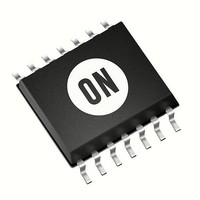
IC LED DRIVER RGB 14-TSSOP

NCP5623DTBR2G

Manufacturer Part Number
NCP5623DTBR2G
Description
IC LED DRIVER RGB 14-TSSOP
Manufacturer
ON Semiconductor
Type
RGB LED Driverr
Datasheet

Specifications of NCP5623DTBR2G

Topology
PWM, Switched Capacitor (Charge Pump)
Number Of Outputs
3
Internal Driver
Yes
Type - Primary
Backlight, Flash/Torch
Type - Secondary
RGB, White LED
Frequency
800kHz ~ 1.2kHz
Voltage - Supply
2.7 V ~ 5.5 V
Voltage - Output
4.4 V ~ 5.7 V
Mounting Type
Surface Mount
Package / Case
14-TSSOP
Operating Temperature
-40°C ~ 85°C
Current - Output / Channel
90mA
Internal Switch(s)
Yes
Efficiency
94%
Operating Supply Voltage
2.7 V to 5.5 V
Maximum Supply Current
350 uA
Maximum Power Dissipation
235 mW
Maximum Operating Temperature
+ 125 C
Mounting Style
SMD/SMT
Minimum Operating Temperature
- 40 C
Lead Free Status / RoHS Status
Lead free / RoHS Compliant

Available stocks

Company
Part Number
Manufacturer
Quantity
Price
Part Number:
NCP5623DTBR2G
Manufacturer:
TE
Quantity:
1 000
Part Number:
NCP5623DTBR2G
Manufacturer:
ON/安森美
Quantity:
20 000
Part Number:
NCP5623DTBR2G
0
Company:
Part Number:
NCP5623DTBR2G
Quantity:
8
Company:
Part Number:
NCP5623DTBR2G
Quantity:
620
NCP5623
Triple Output I2C Controlled
RGB LED Driver
dedicated to the RGB illumination or backlight LCD display.
Features
Typical Applications
© Semiconductor Components Industries, LLC, 2008
October, 2008 − Rev. 6
I2C Port
The NCP5623 mixed analog circuit is a triple output LED driver
2.7 to 5.5 V Input Voltage Range
RGB Function Fully Supported
Programmable Integrated Gradual Dimming
90 mA Total LED Current Capability
Provides Three Independent LED Drives
Support I2C Protocol
This is a Pb−Free Device
Multicolor Illuminations
Portable Back Light
Digital Cellular Phone Camera Photo Flash
LCD and Key Board Simultaneous Drive
+Vcc
MCU
Figure 1. Typical Multiple Color LED Driver
SDA
SCL
GND
1 mF/6.3 V
GND
GND
C1
62 k
+Vbat
R1
13
12
10
11
9
6
2
1
Vbat
Vdet
SDA
SCL
IREF
GND
GND
IC NC NC IC
NCP5623
7
U1
8 14
LED1
LED2
LED3
5
4
3
GND
6
2
5
LRTB−G6T
1 mF/6.3 V
D1
C2
R
G
B
1
1
3
4
+5 V
14
†For information on tape and reel specifications,
NCP5623DTBR2G
including part orientation and tape sizes, please
refer to our Tape and Reel Packaging Specification
Brochure, BRD8011/D.
(Note: Microdot may be in either location)
Device
ORDERING INFORMATION
5623
A
L
Y
W
G
1
http://onsemi.com
= Specific Device Code
= Assembly Location
= Wafer Lot
= Year
= Work Week
= Pb−Free Package
CASE 948G
TSSOP−14
TSSOP−14
(Pb−Free)
Package
Publication Order Number:
14
1
MARKING
DIAGRAM
Tape & Reel
Shipping
NCP5623/D
ALYWG
2500 /
5623
G

Related parts for NCP5623DTBR2G

NCP5623DTBR2G Summary of contents

Page 1

... Pb−Free Package (Note: Microdot may be in either location) ORDERING INFORMATION Device Package Shipping NCP5623DTBR2G TSSOP−14 (Pb−Free) Tape & Reel †For information on tape and reel specifications, including part orientation and tape sizes, please refer to our Tape and Reel Packaging Specification Brochure, BRD8011/D ...

Page 2

Vbat 1 mF/6 GND 6 GND DIGITAL CONTROL SDA 9 SCL 11 Vbat R1 ANALOG 10 FUNCTIONS 62 k GND TSSOP− GND Vbat 2 Vdet LED3 3 12 LED2 11 SCL ...

Page 3

PIN ASSIGNMENT Pin Name Type GND POWER 3 LED3 OUTPUT, POWER 4 LED2 OUTPUT, POWER 5 LED1 OUTPUT, POWER 6 GND ANALOG GROUND SDA INPUT, DIGITAL 10 I ANALOG REF 11 SCL INPUT, ...

Page 4

MAXIMUM RATINGS Symbol V Power Supply (see Figure 4) bat SDA, SCL Digital Input Voltage ESD Human Body Model 1500 100 pF (Note 3) Machine Model P Power Dissipation @ T D Thermal Resistance Junction ...

Page 5

ANALOG SECTION: (Typical values are referenced +25°C, Min & Max values are referenced −40°C to +85°C ambient temperature, unless otherwise A noted), operating conditions 2.85 V < V bat Pin Symbol 10 I Reference current @V REF ...

Page 6

LED MAXIMUM CURRENT CALCULATION The load current is derived from the 600 mV reference voltage provided by the internal Band Gap associated to the external resistor connected across I REF Note : due to the internal structure of this pin, ...

Page 7

B[7:5] : Internal Register Selection The contain of bits B[4:0] depends upon the type of function selected by bits B[7:5] as ...

Page 8

Table 2. Basic Programming Sequences I2C Address COMMAND Bits[7:0] $70 000X XXXX $70 0010 0000 0011 1111 $70 0100 0000 0101 1111 $70 0110 0000 0111 1111 $70 1000 0000 1001 1111 $70 1010 0000 1011 1111 $70 1100 0000 ...

Page 9

Figure 5. Output Current Programmed Value ( ILED = F(Step) ) PWM OPERATION The built−in PWM are fully independent and can be programmed to any value during the normal operation of the ...

Page 10

... Pb−Free strategy and soldering details, please download the ON Semiconductor Soldering and Mounting Techniques Reference Manual, SOLDERRM/D. ON Semiconductor and are registered trademarks of Semiconductor Components Industries, LLC (SCILLC). SCILLC reserves the right to make changes without further notice to any products herein ...

Related keywords