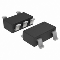
NCP5006SNT1G ON Semiconductor, NCP5006SNT1G Datasheet - Page 8

NCP5006SNT1G
Manufacturer Part Number
NCP5006SNT1G
Description
IC LED BOOST DRIVER SOT23-5
Manufacturer
ON Semiconductor
Type
Backlight, White LEDr
Datasheet
1.NCP5006SNT1G.pdf
(24 pages)
Specifications of NCP5006SNT1G
Constant Current
Yes
Topology
PWM, Step-Up (Boost)
Number Of Outputs
1
Internal Driver
Yes
Type - Primary
Backlight
Type - Secondary
White LED
Voltage - Supply
2.7 V ~ 5.5 V
Voltage - Output
24V
Mounting Type
Surface Mount
Package / Case
TSOT-23-5, TSOT-5, TSOP-5
Operating Temperature
-25°C ~ 85°C
Current - Output / Channel
50mA
Internal Switch(s)
Yes
Efficiency
90%
Number Of Segments
5
Operating Supply Voltage
2.7 V to 5.5 V
Maximum Power Dissipation
160 mW
Maximum Operating Temperature
+ 85 C
Mounting Style
SMD/SMT
Minimum Operating Temperature
- 25 C
Led Driver Application
Keyboard Backlight, LED Displays
No. Of Outputs
1
Output Current
50mA
Output Voltage
24V
Input Voltage
2.7V To 5.5V
Dimming Control Type
PWM
Rohs Compliant
Yes
Lead Free Status / RoHS Status
Lead free / RoHS Compliant
Frequency
-
Lead Free Status / Rohs Status
Details
Other names
NCP5006SNT1G
NCP5006SNT1GOSTR
NCP5006SNT1GOSTR
Available stocks
Company
Part Number
Manufacturer
Quantity
Price
Company:
Part Number:
NCP5006SNT1G
Manufacturer:
ON
Quantity:
3 000
Part Number:
NCP5006SNT1G
Manufacturer:
ON/安森美
Quantity:
20 000
Output Current Range Set−Up
drop across the sense resistor R1. The voltage drop is
constantly monitored internally, and maximum peak
current allowed in the inductor is set accordingly in order
to keep constant this voltage drop (and thus the current
flowing through the LED). For example, should one need
a 10 mA output current, the sense resistor should be sized
according to the following equation:
The current regulation is achieved by means of an external sense resistor connected in series with the LED string.
The current flowing through the LED creates a voltage
R 1 + Feedback Threshold
I out
Pulse
GND
+ 200 mV
FB
3
10 mA
22 W
GND
R1
+ 20 W
CONTROLLER
Figure 9. Basic Schematic Diagram
Figure 8. Output Current Feedback
LWT67C LWT67C LWT67C LWT67C LWT67C
4
2
3
http://onsemi.com
D6
V
(eq. 9)
bat
NCP5006
U1
EN
GND
FB
NCP5006
8
D5
V
V
22 mH
yields 9.09 mA, good enough to fulfill the back light
demand. The typical application schematic diagram is
provided in Figure 9.
L1
bat
out
A standard 5% tolerance resistor, 22 W SMD device,
GND
5
1
D4
Q1
V
V
out
1
bat
D3
L1
22 mH
MBR0530
D1
4.7 mF
R1
xW
C1
D1
D2
GND
GND
GND
C2
1.0 mF


